SB-220/221 Tuned Input Modification
A deep dive into the tuned input circuitry of Heathkit amplifiers
Last Update: July 5, 2023
Introduction
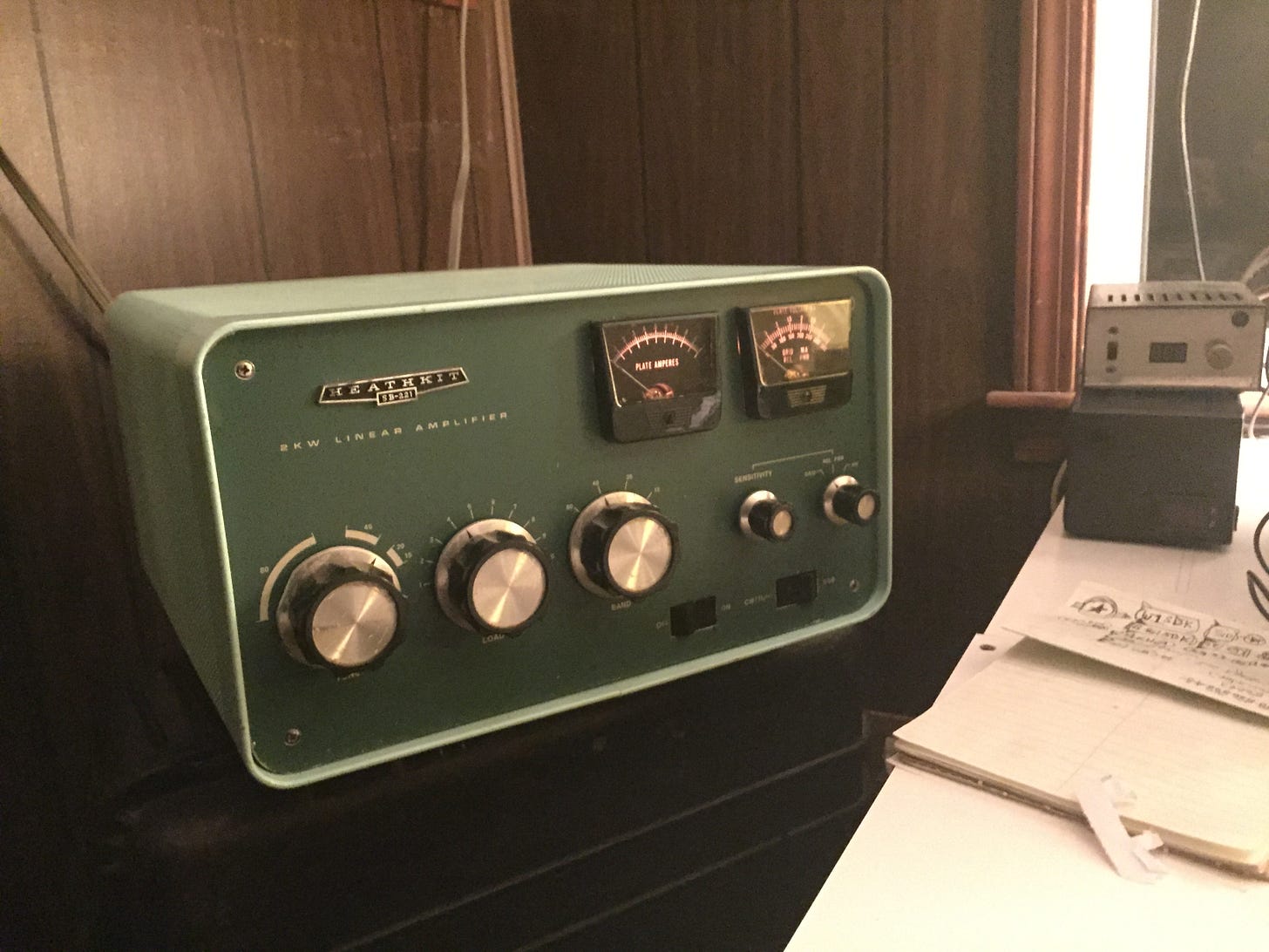
Heathkit’s SB-220/221 amplifiers use low-pass pi circuits to achieve a 1:1 match with the rigs that excite them. These pi circuits use slug-tuned coils wired to the bandswitch located behind the amplifier’s front panel. To adjust them, the front panel has to be off while the amplifier is being operated at full power output. Perhaps for this reason, Heathkit “pre-tuned” the slug coils “at the factory” so that customers didn’t have to adjust them.
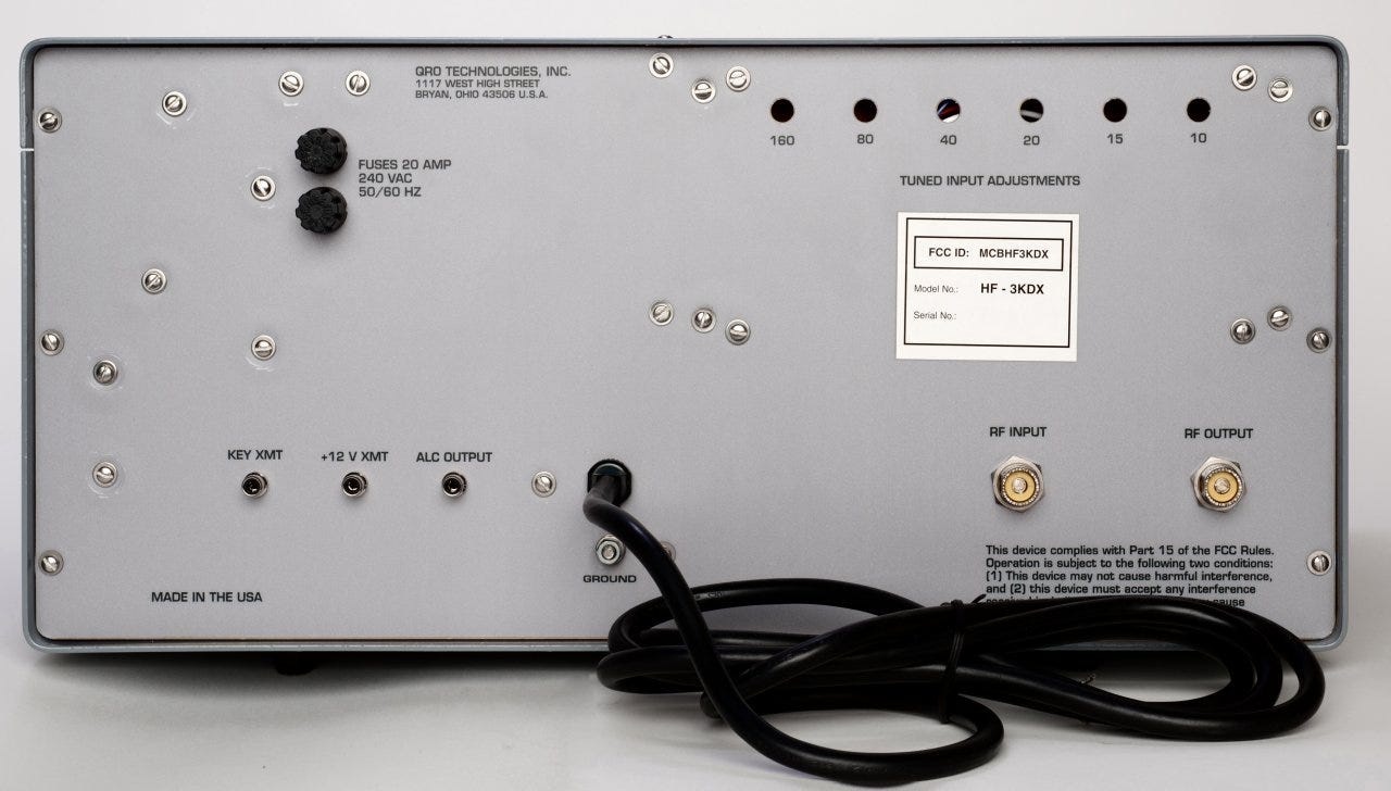
Other manufacturers enabled tuned input circuitry to be safely adjusted on the rear panel while the amplifier is operated at full power.1
Driving the Amplifier Through a Tuner
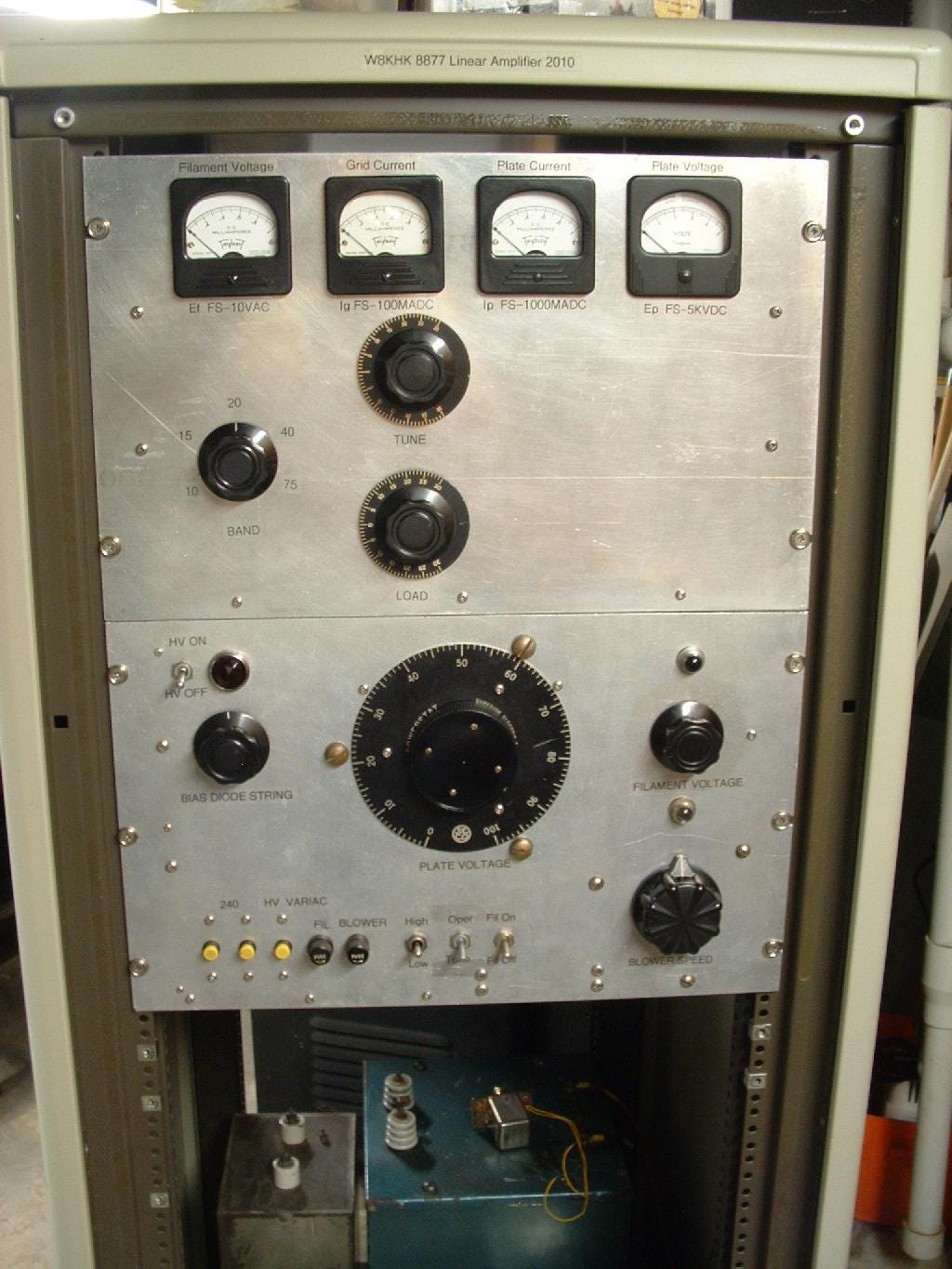
In the homemade amplifier seen below, K1JJ does not include any tuned input circuitry. Instead, he drives the 8877 through an external LC network, keeping the coaxial cable between it and the tube input as short as possible.
Many hams use automatic antenna tuner—oftentimes located inside the rig—establishing a 1:1 “perfect match” seen by the exciter when driving the linear amplifier. As W8JI points out, “If the amplifier contains a proper low-pass tuned input, and impedance is close but not quite right for your exciter, there is nothing wrong with using an external tuner”.
Heathkit Factory Input Wiring
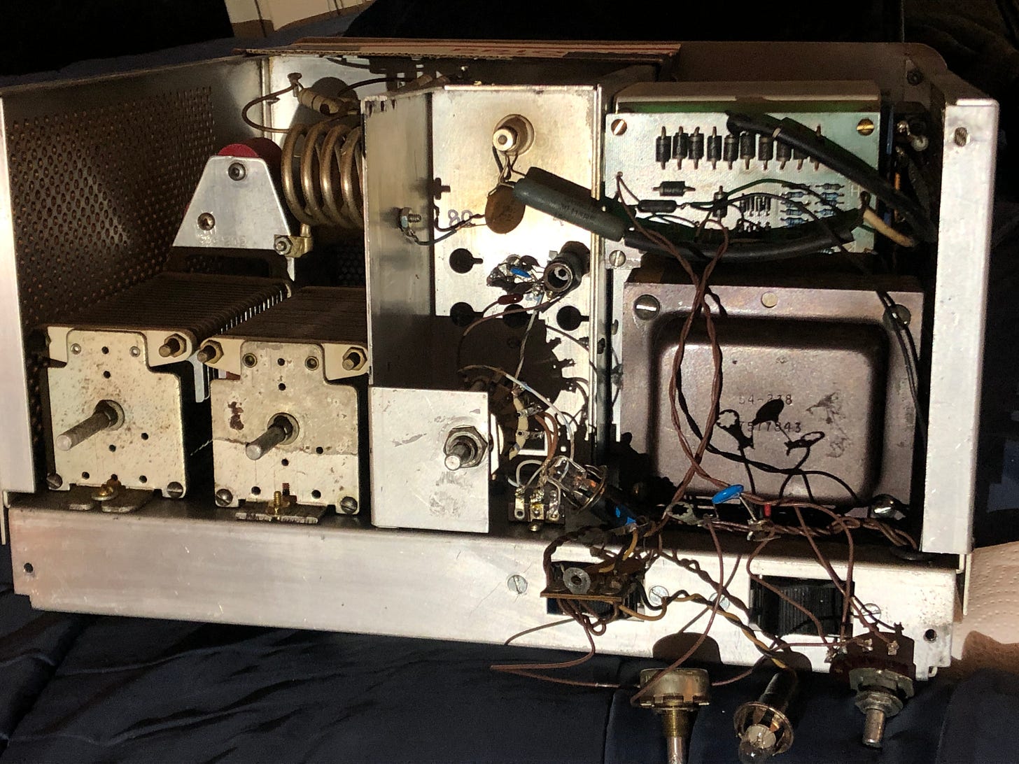
Since the tuned input circuit in Heathkit’s SB-series of amplifiers is situated behind the front panel, a length of coax connects it to the 3-500Z tubes in the rear of the cabinet. This cable’s capacitance is added to the output capacitance of the tuned input circuits used on different bands. This can increase the amount of drive required for full power output on the higher bands.2
SB-221 to SB-220 Conversions
Matching the tuned input circuit to the 3-500Z tubes becomes even more convoluted when converting a SB-221 into a SB-220. This is because Heathkit placed a “CB filter” (FL1) between the tuned input circuit and the 3-500Z tubes to prevent the SB-221 from being used on the CB band. This causes the values of capacitors and inductors in the SB-221 tuned input circuit to differ from those used in the SB-220. Thus, when the “CB filter” is removed from a SB-221, the component values of its tuned input circuit should be matched to those found in a SB-220.3
Although it is possible to rewind SB-221 slug-tuned coils to SB-220 values on 80 through 20 meters,4 one needs SB-220 mica capacitors values not found in the SB-221. And, of course, one must also acquire the five-position bandswitch and two additional input coils to operate the amplifier on the 15 and 10 meter bands.5
With all of these complications, one might be tempted to redesign the SB-221 tuned input circuit entirely—perhaps even broadening it to include true WARC band functionality.
Alternative Tuned Input Scheme
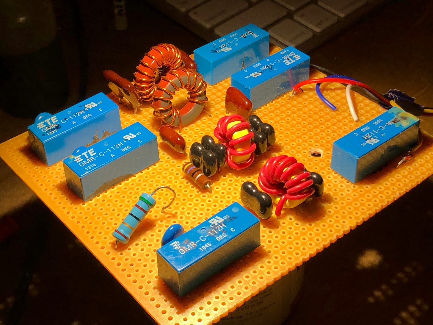
The first order of business might be to rebuild the tuned input circuit on a PC board so that it can be relocated next to the 3-500Z tubes so that a coaxial cable is not needed between them. Such a PC board can be fitted in the empty space next to the tube sockets underneath the amplifier chassis.
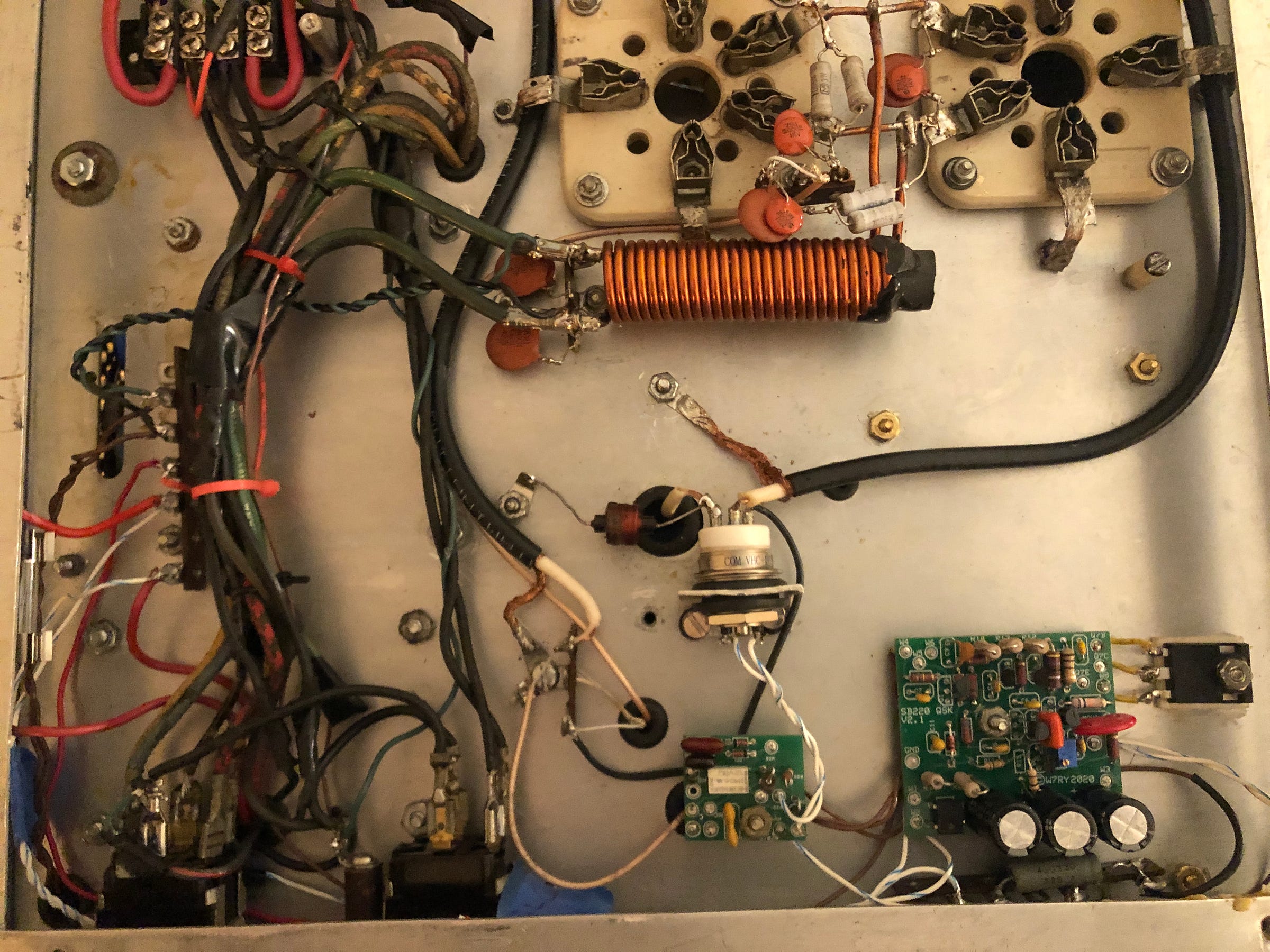
This scheme requires rewiring the front section of the bandswitch acutate relays selecting various pi circuits on the PC board.
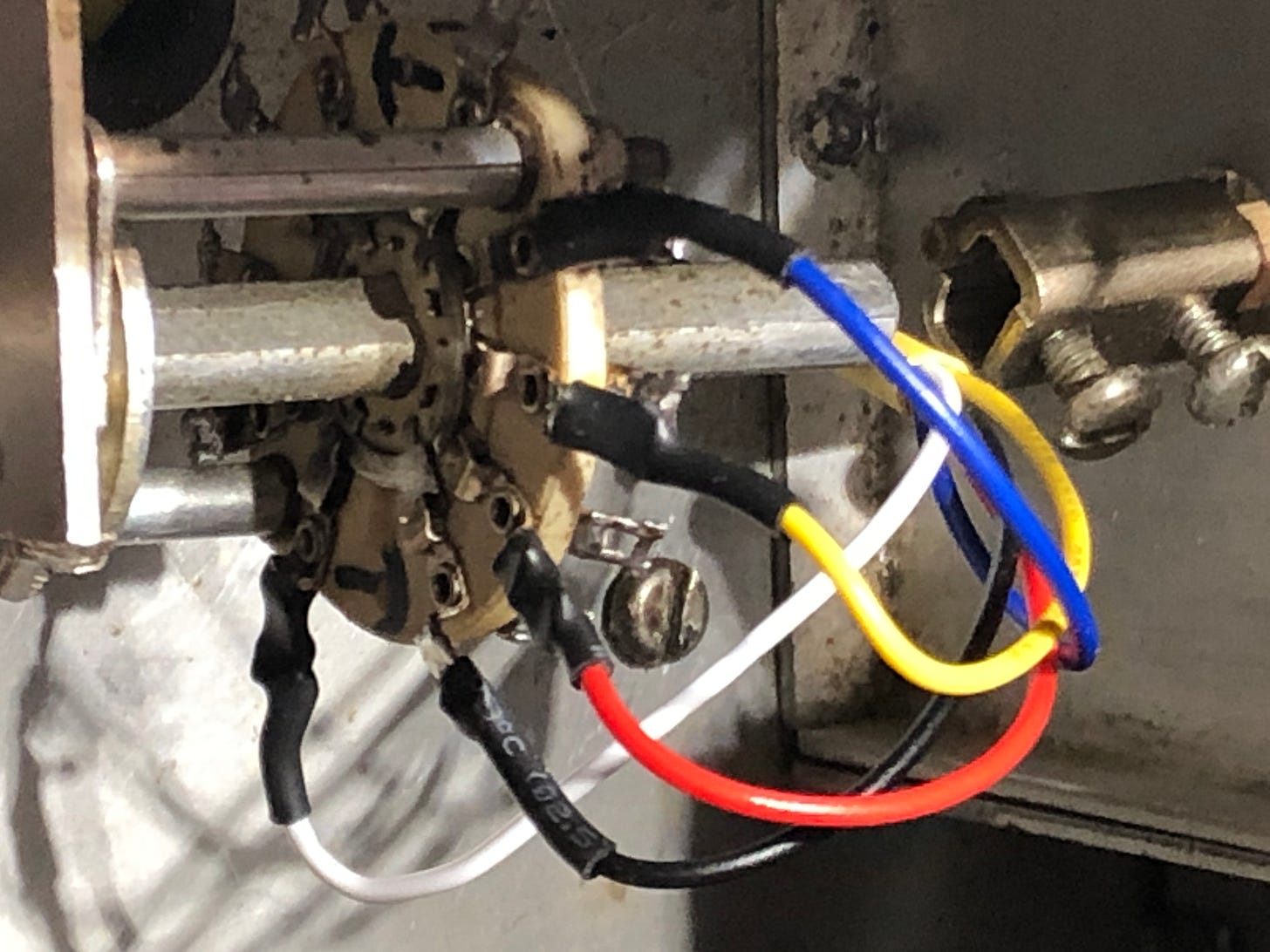
On First Blush
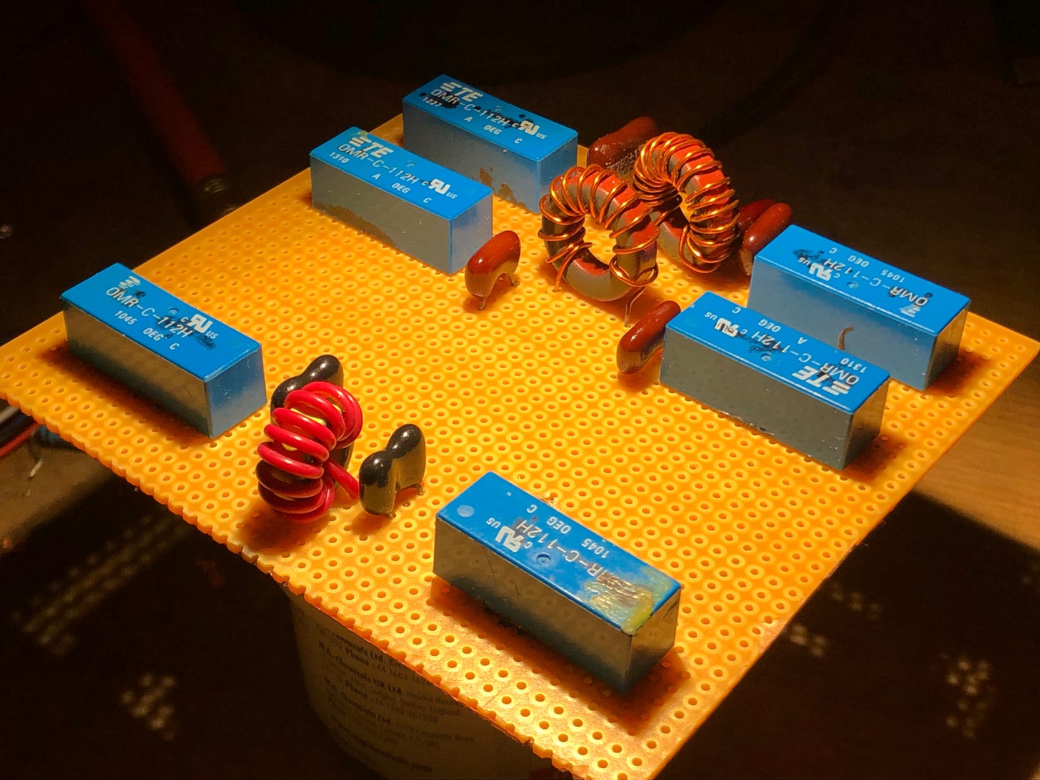
On first blush, it might be possible to migrate SB-220 tuned input components onto a PC board, as attempted below.
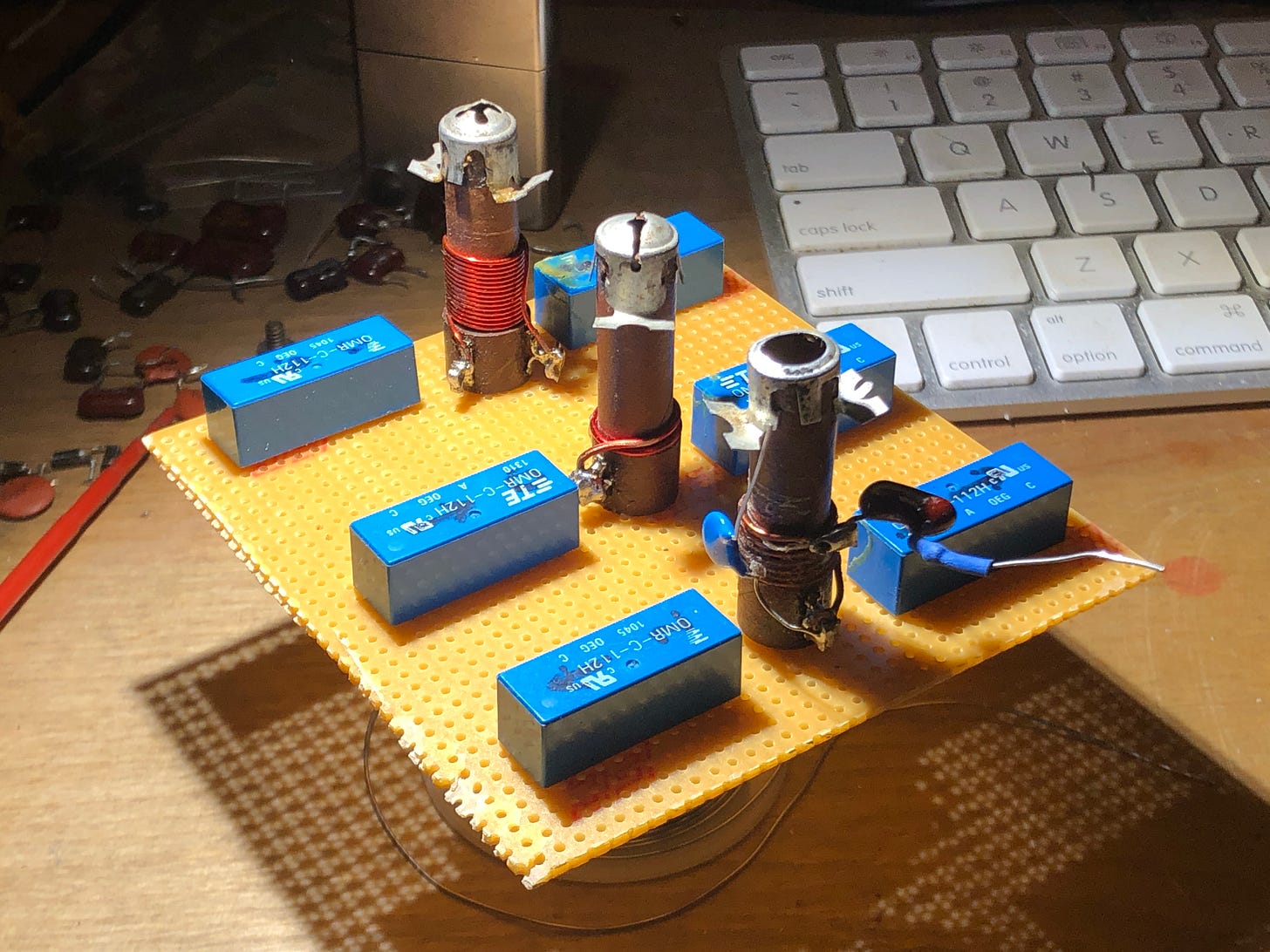
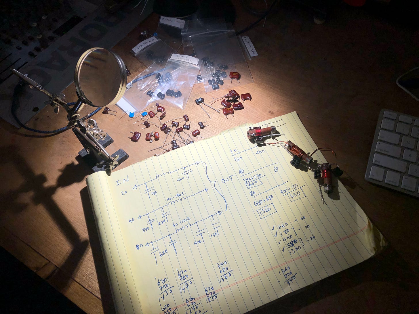
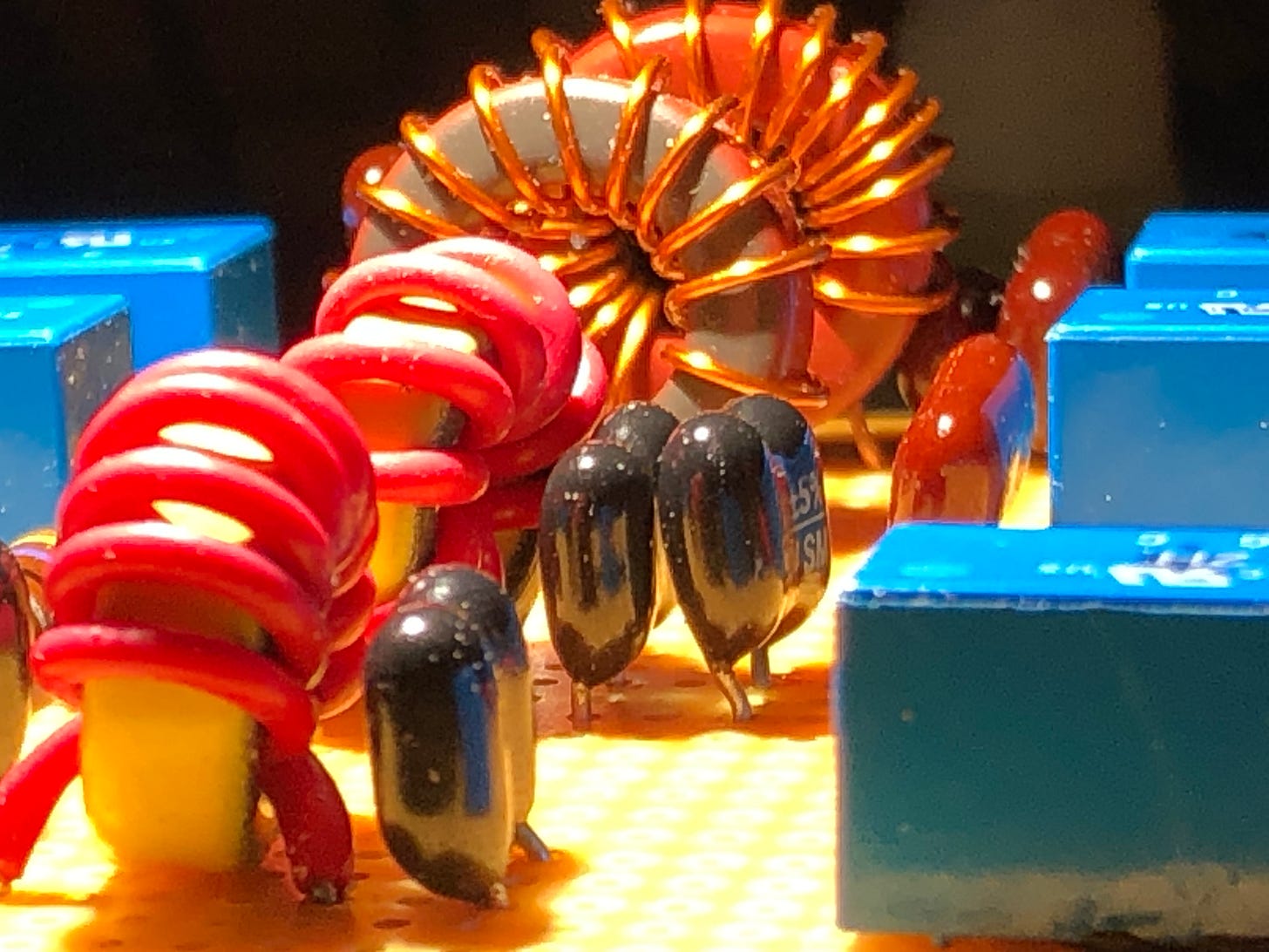
Unfortunately, Heathkit's slug-tuned coils are too tall to fit under the chassis. The workaround would be to replace them with toroid coils. This enables us use new pi-circuit capacitor and inductor component values, such as those employed by WD7S (SK) in his series of unobtainium tuned input boards.
Let’s Go Down the Rabbit Hole!
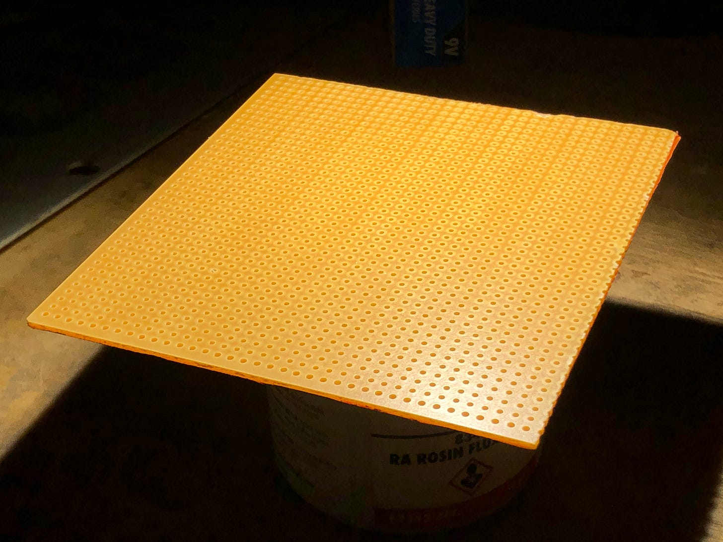
We began with a solderless perfboard cut to dimensions that fit the space next to the 3-500Z tube sockets.
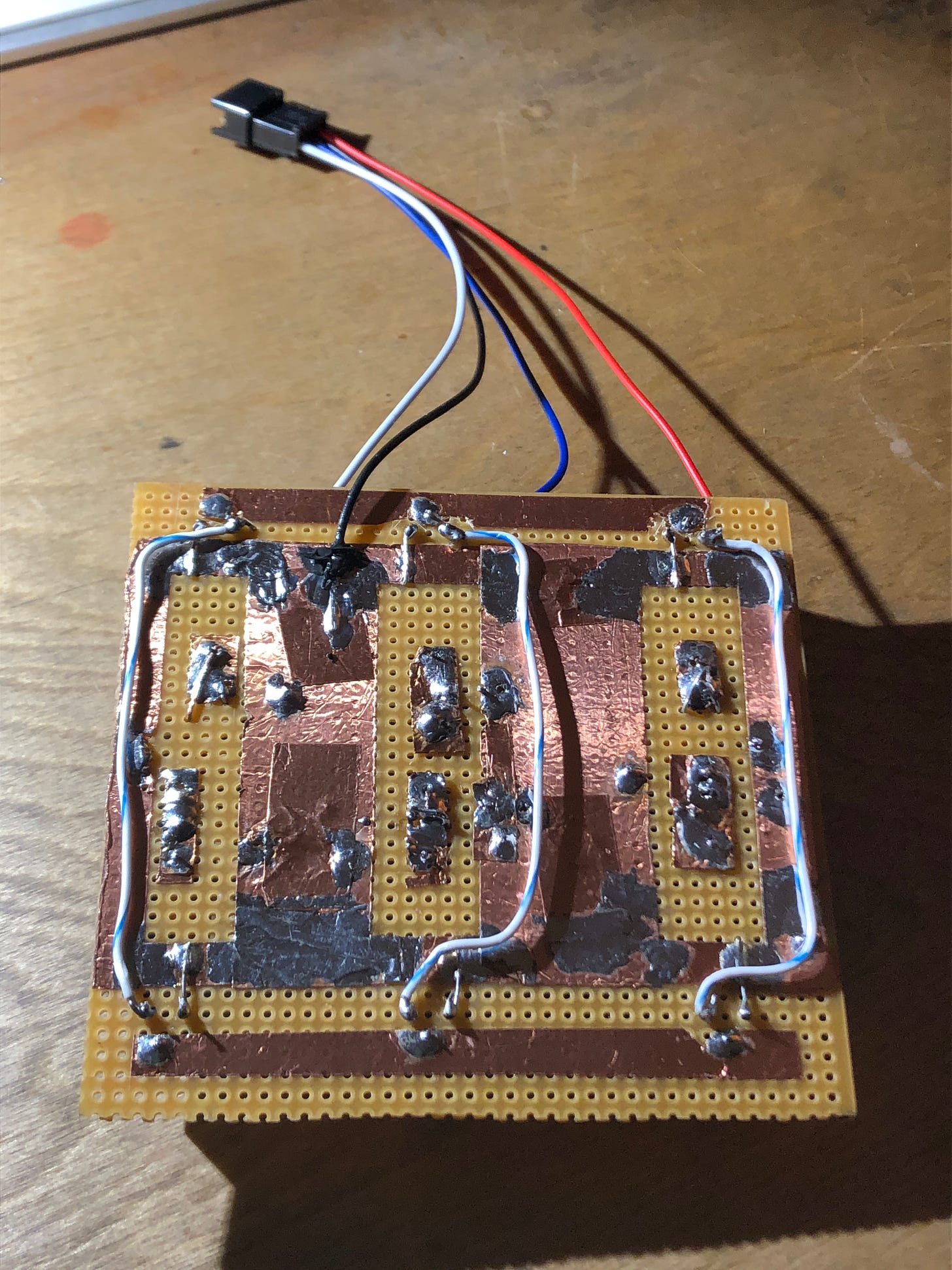
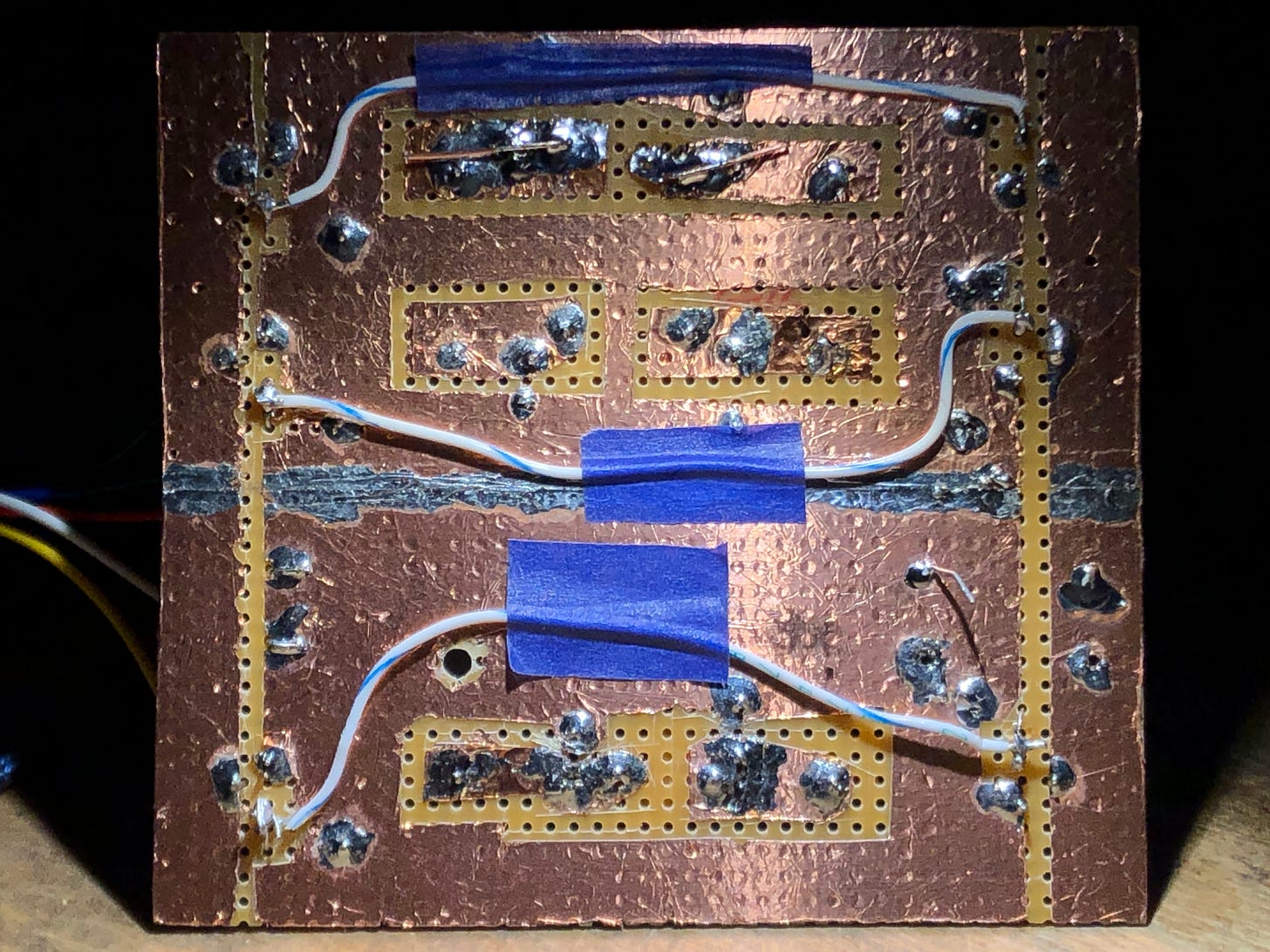
Copper foil tape is then affixed to one side to create a RF ground plane.6 Any seams must be soldered because the adhesive side of the copper foil tape does not make a good RF connection.

Components are mounted by piercing their leads through the copper foil tape and then soldering them to it.
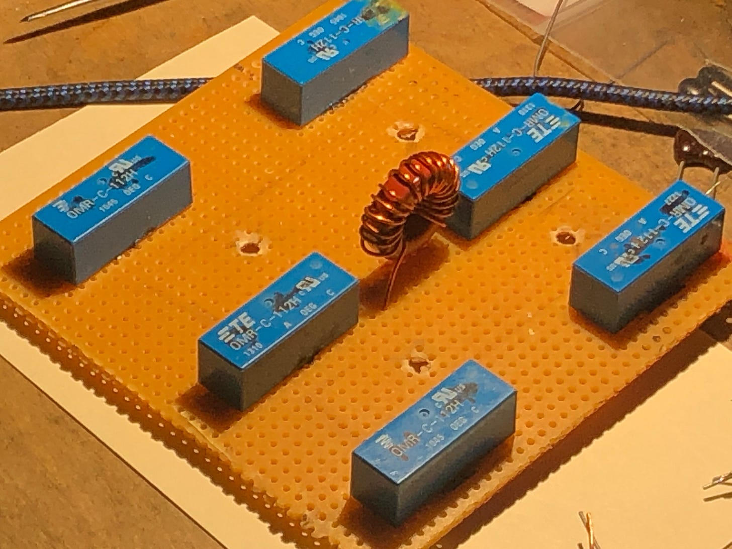
After soldering the components to the copper foil, their leads are connected in accordance with the schematic by cutting away copper foil with an Xacto knife.
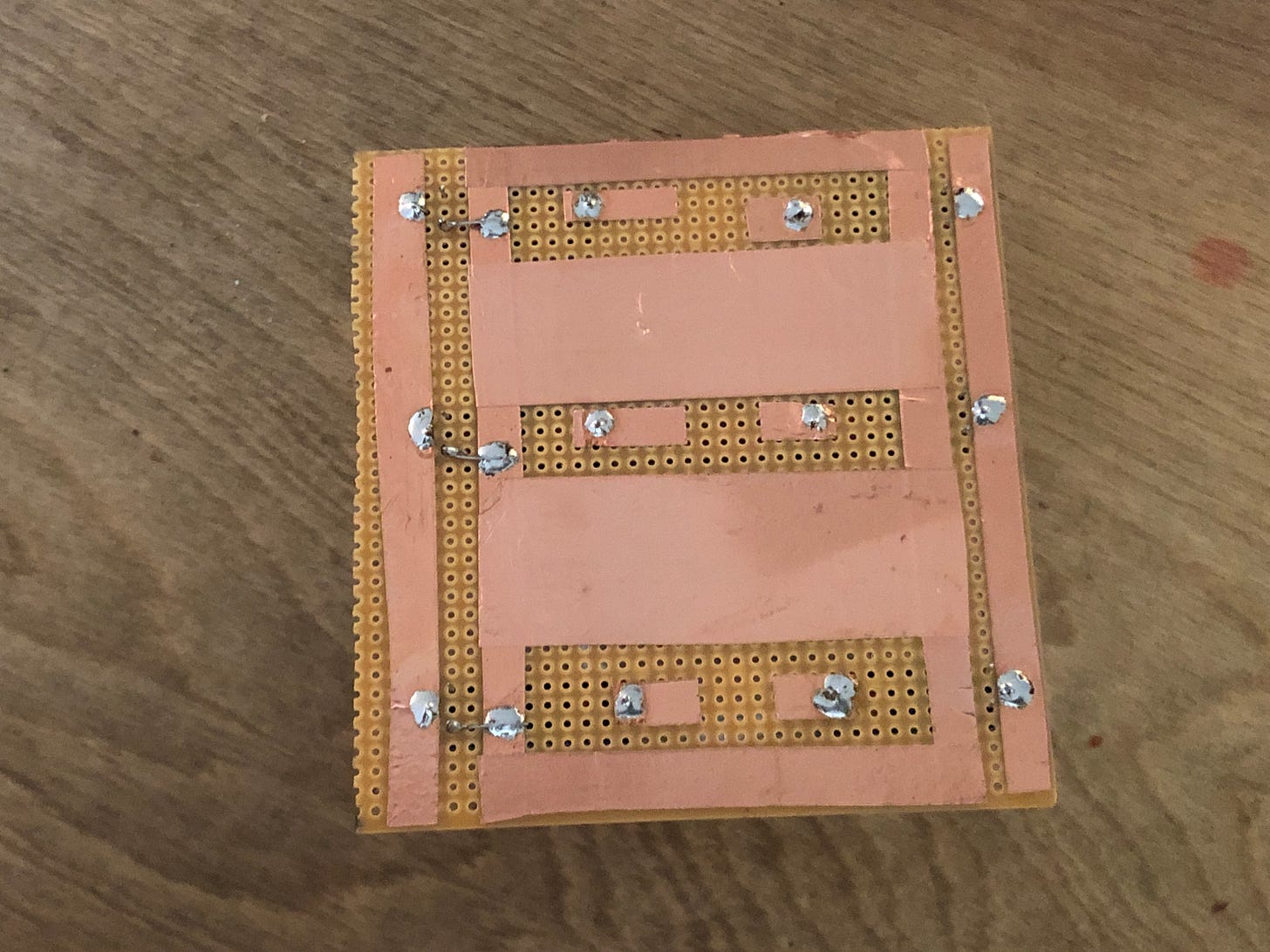
Our Parts List
The parts list for this tuned input board is provided below.
29 - 24 MHz: Cin = 100 pfd | Cout = 100 pfd | L = 7T #20 on T50-6
21 - 28 MHz: Cin = 150 pfd | Cout = 150 pfd | L = 8T #20 on T50-6
14 - 10 MHz: Cin = 220 pfd | Cout = 220 pfd | L = 11T #20 on T50-6
7 MHz: Cin = 470 pfd | Cout = 420 pfd | L = 13T #20 on T68-2
3.5 MHz: Cin = 820 pfd | Cout = 750 pfd | L = 17T #22 on T68-2
Toroid Cores: (3) T50-6; (2) T68-2 cores are required for 80-10 Meters.
Mica Capacitors: (2) 100 pfd; (2) 150 pfd; (2) 220 pfd; (1) 470 pfd; (1) 420 pfd; (1) 820 pfd; (1) 750 pfd.
Now We Get to Play with a NANO VNA
We terminate the output of the board with a non-inductive 50 Ohm resistor, and sweep its input SWR with a NANO VNA.
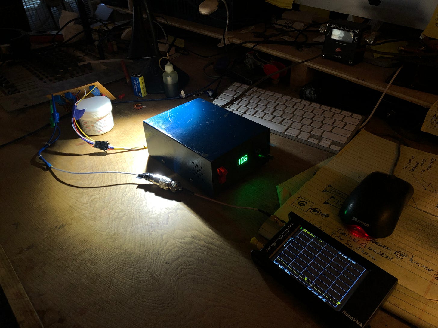
Initial SWR Sweeps
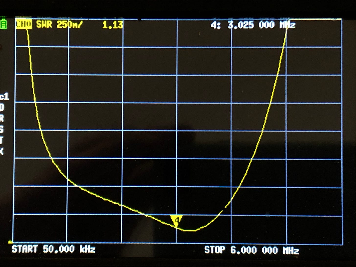
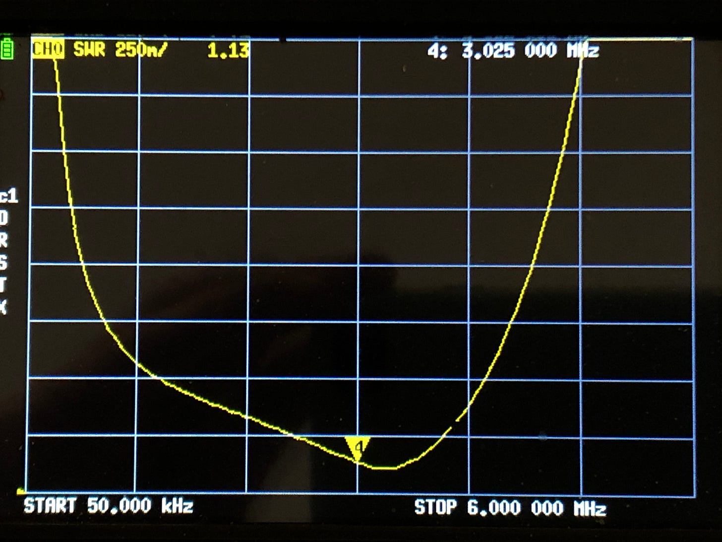
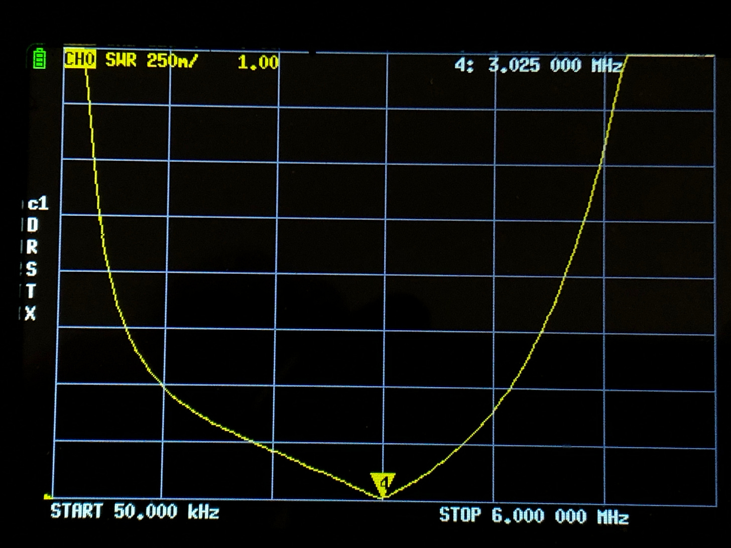
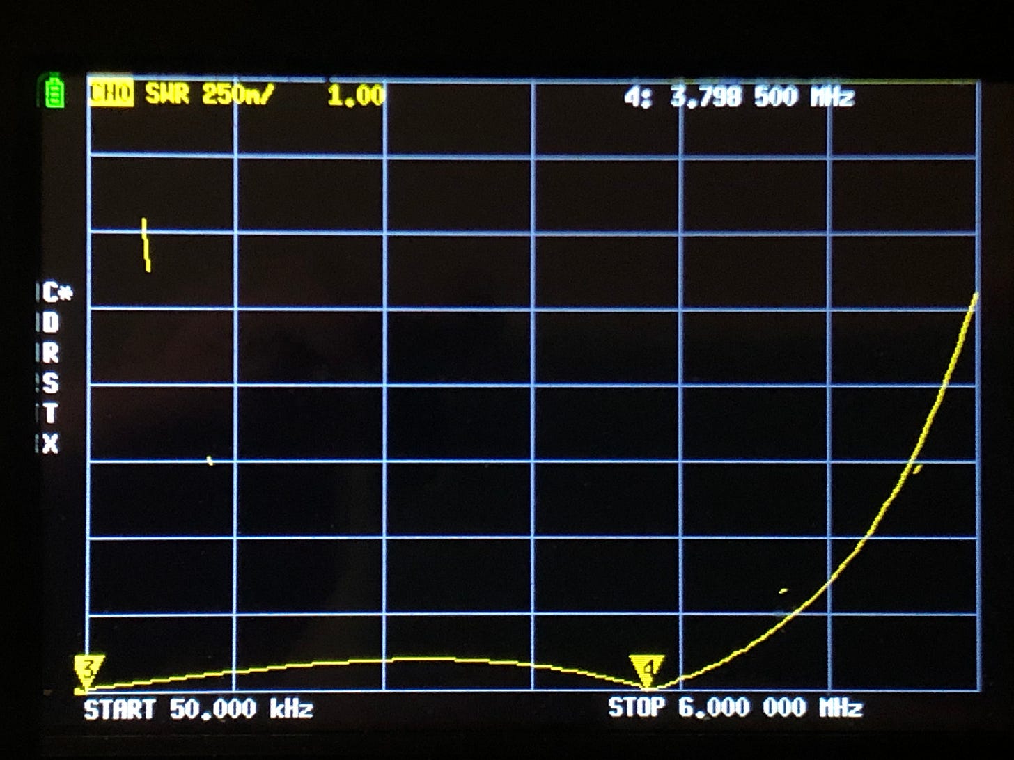
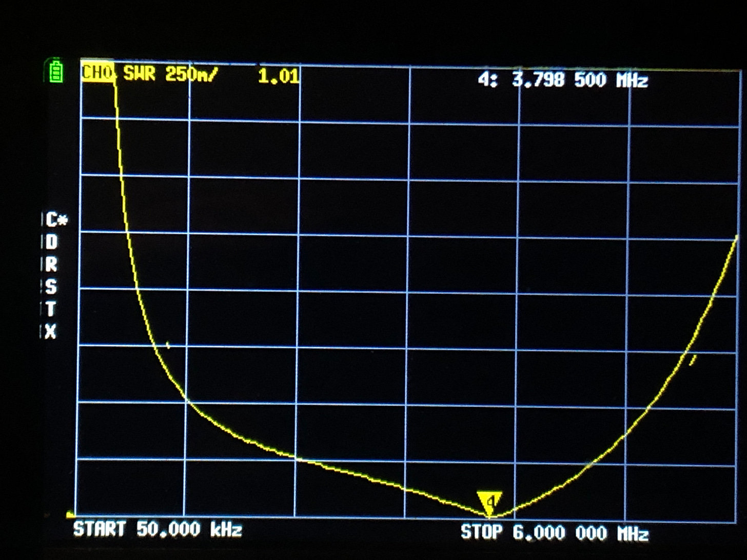
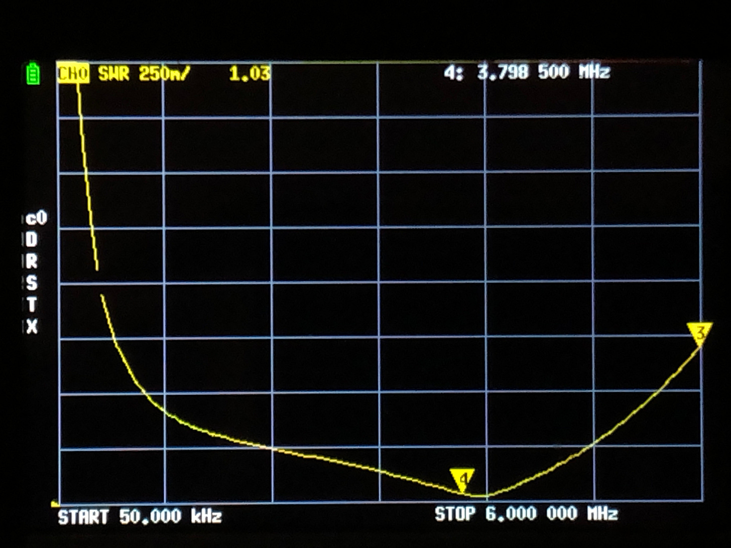
Futzing around with toroid coil wire spacings produces the SWR sweeps seen below.
Second SWR Sweeps
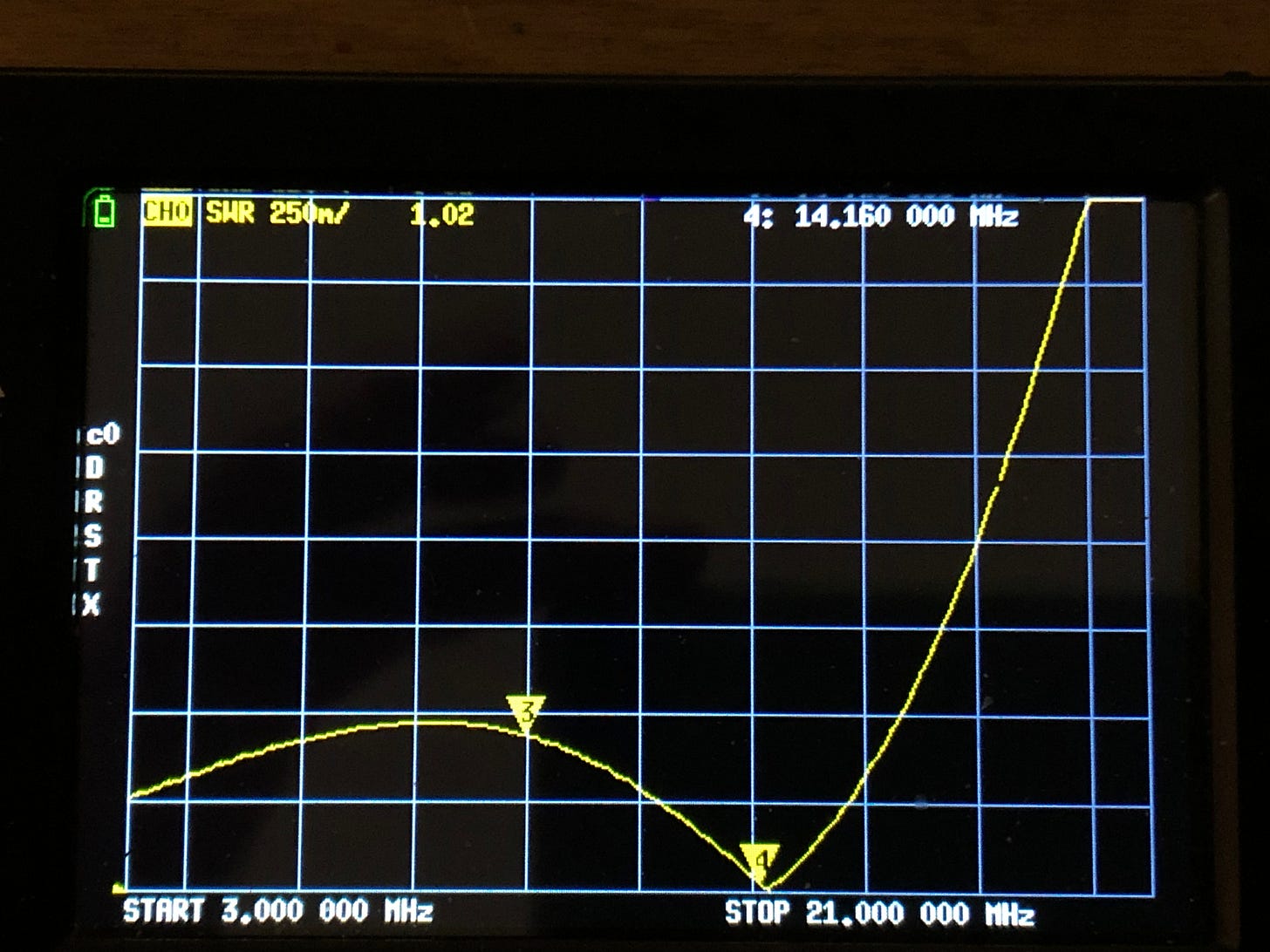
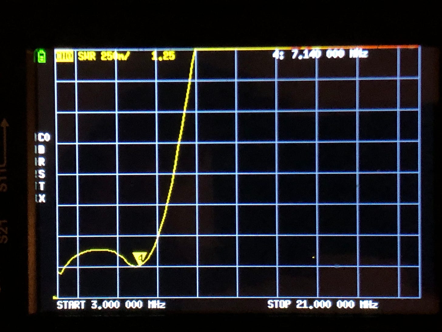
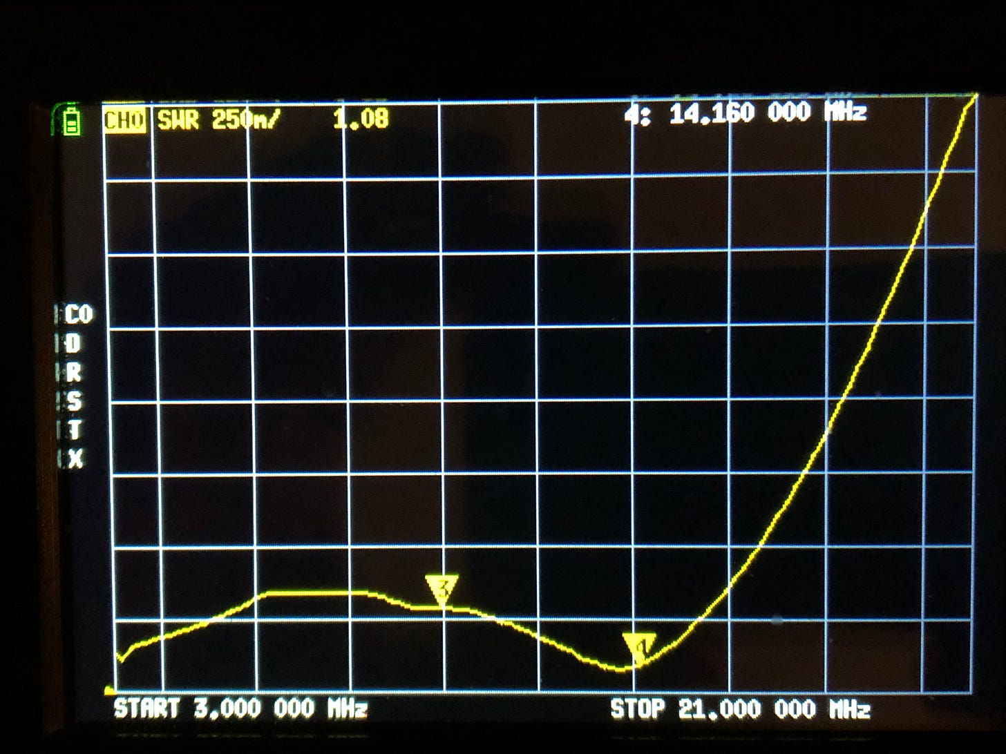
This shows it is possible to use copper foil to construct these pi circuits on a piece of perfboard. The next step is to wire this "prototype board" into the SB-221 amplfier to see if the SWR sweeps are affected. With both tubes plugged into the sockets, each filament tied to ground through a 100 Ohm resistor, the prototype board’s input is again swept with the NANO VNA.7 This produces the SWR curves, below.
Wassup wid DaT?
When the input of the prototype board is connected to the amplifier tubes, the SWR curves acquire a “bumpy” contour. Although the SWR minima remain parked on the same frequencies, their values are raised.
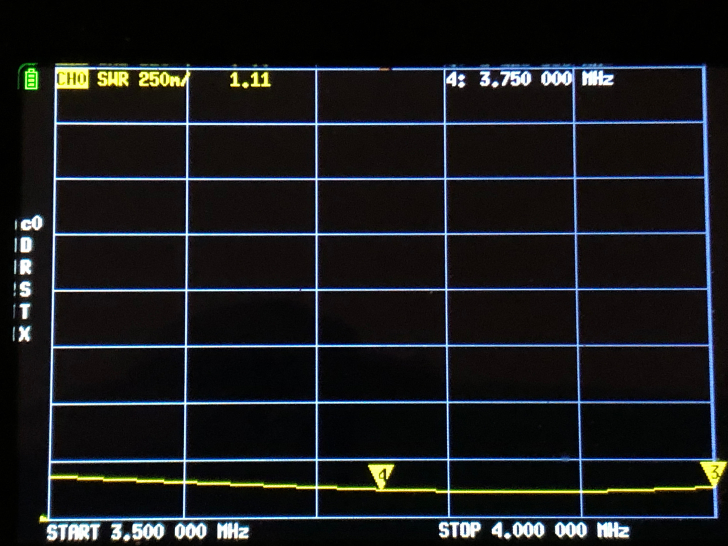
80 Meters: 1.10 to 1 => 1.38 to 1
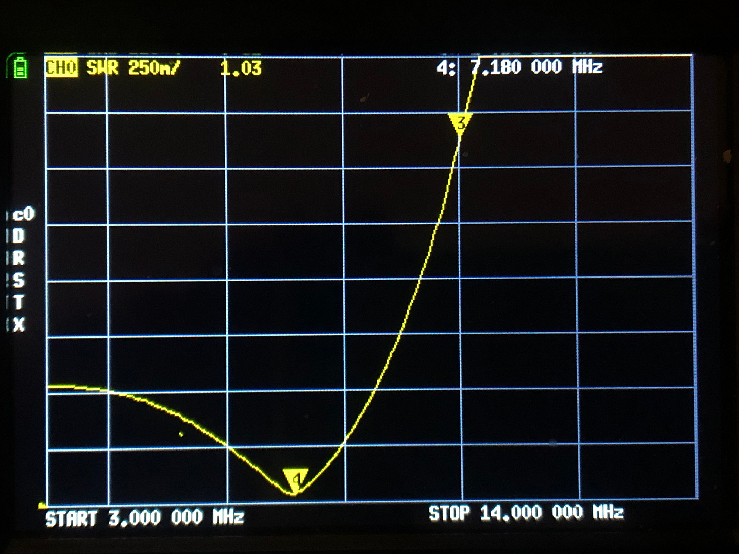
40 Meters: 1.03 to 1 => 1.25 to 1
20 Meters: 1.02 to 1 => 1.08 to 1
We’re not sure why this happened. But since the SWRs are all below 1.5 to 1, this may be good enough to go ahead and power up the amplifier see what kind of SWR it offers to the exciter on different bands. For the sake of readers, however, we will see if we can lower the SWR curves by horsing around with contraption before installing it in the SB-221 and testing it.
Before doing this, we opt to migrate components to a larger piece of perfboard so that we can add a 15 meter pi circuit to it.
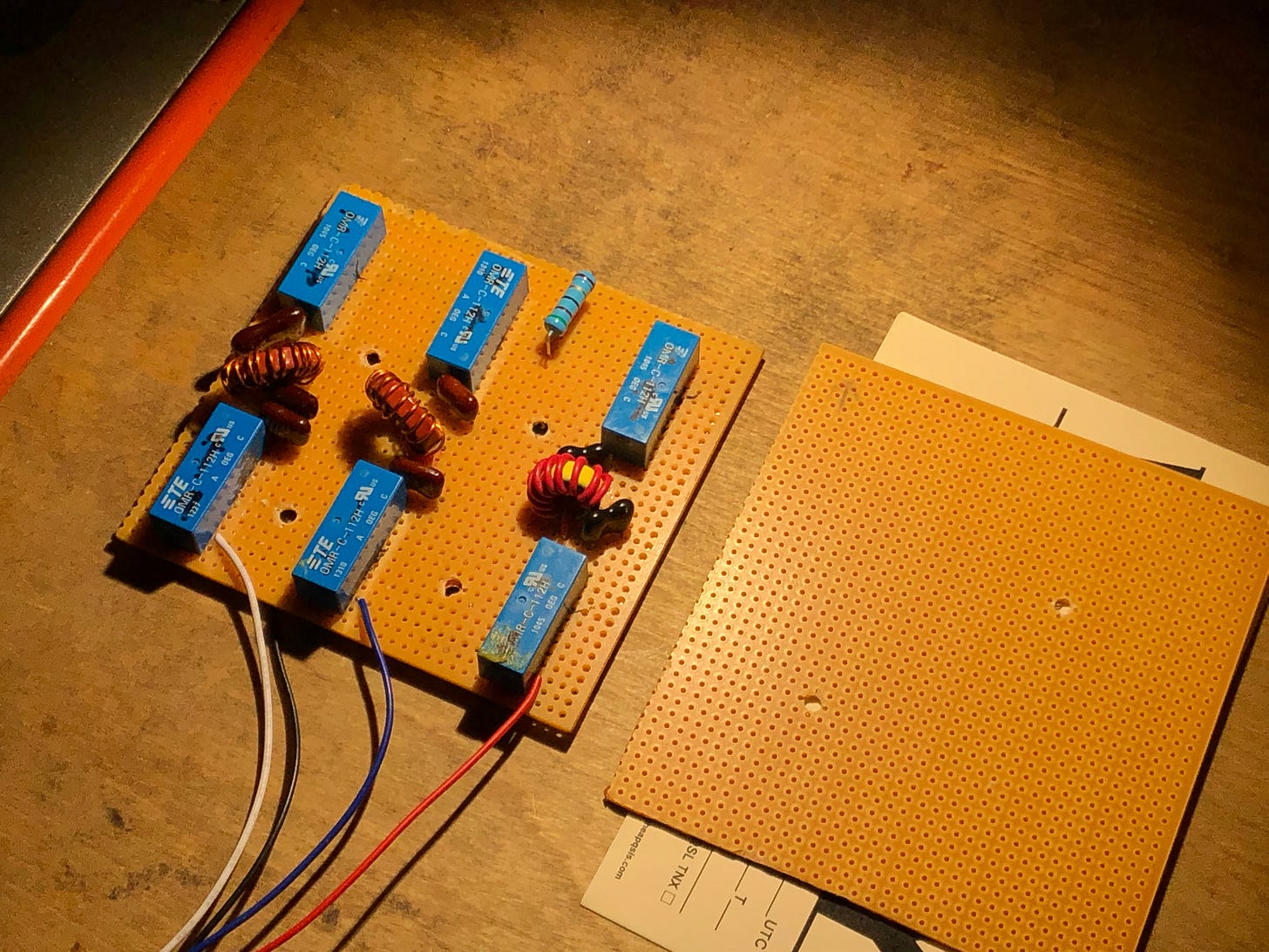
Pi circuits tuned during the prototype stage work perfectly on the new board when swept by the NANO VNA. This tells us our construction techniques are good at HF operation.
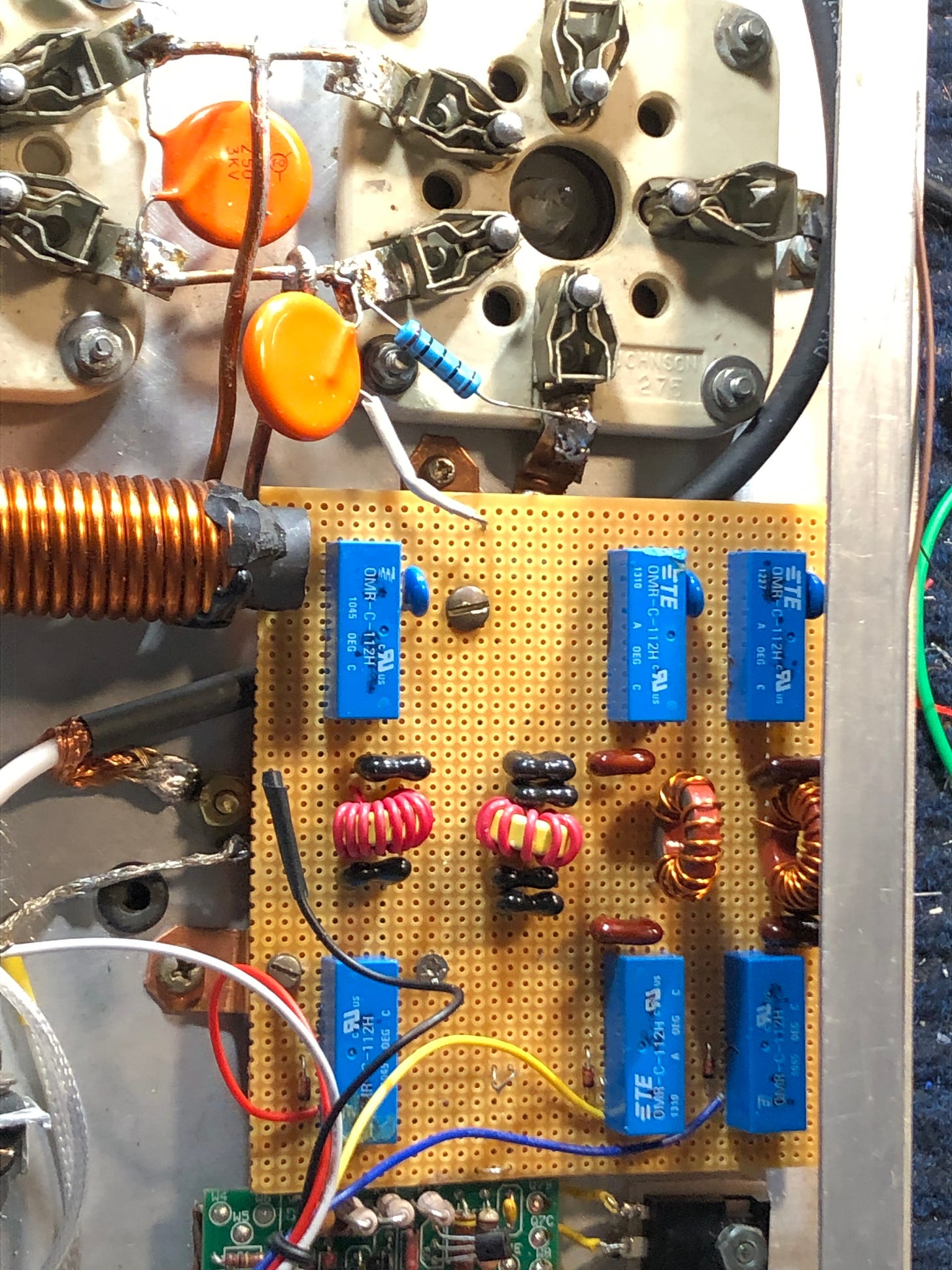
Below we see the completed “production board”.8
A nit-picky sidenote: 1N914 diodes are reverse-biased across relay coils along with 0.1 ufd bypass capacitors to ground to suppress EMF voltage spikes resulting from operation of the relays. Readers can compare the undersides of the prototype and “production board”, below.
Low Inductance RF Grounding Straps
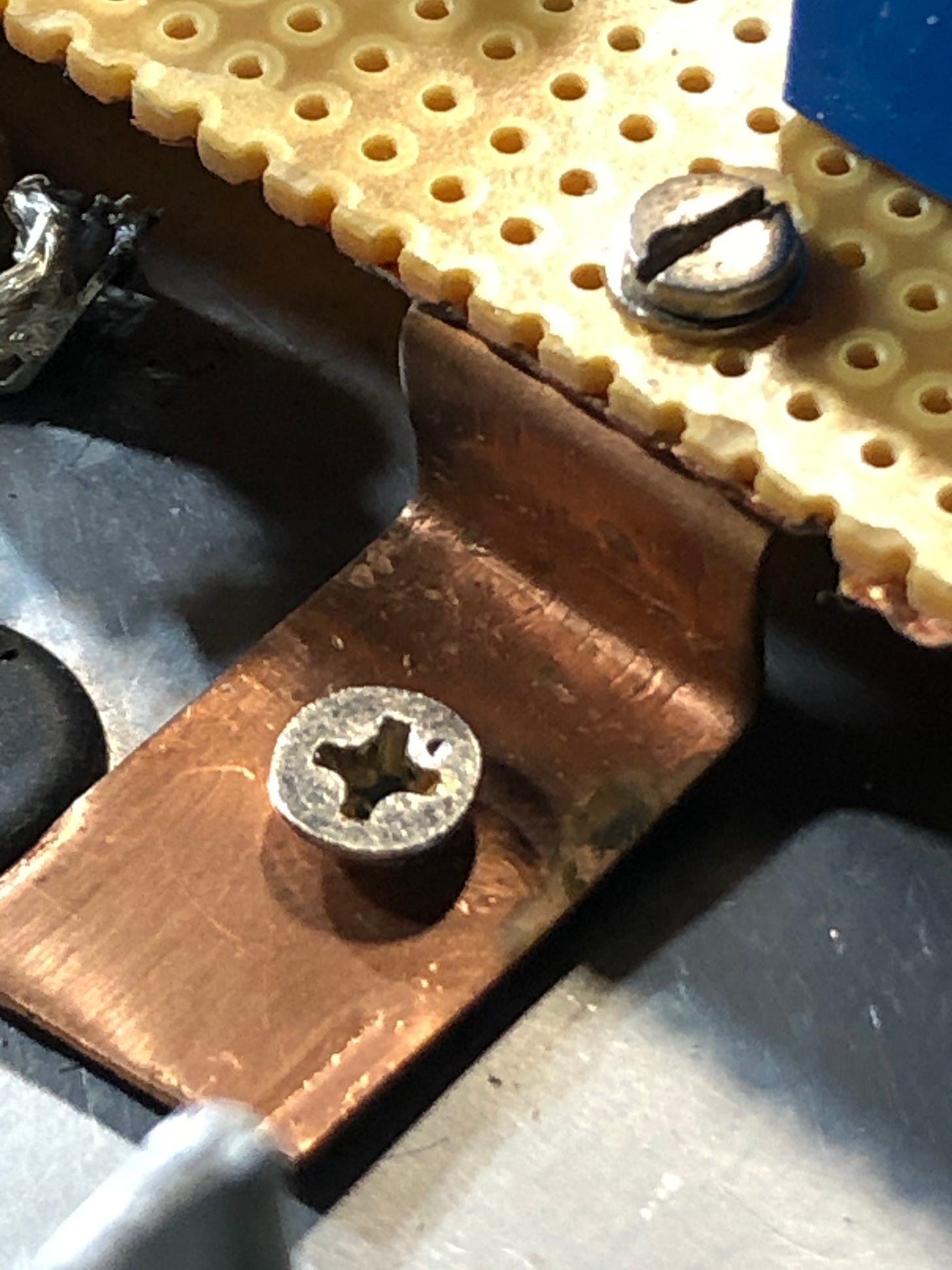
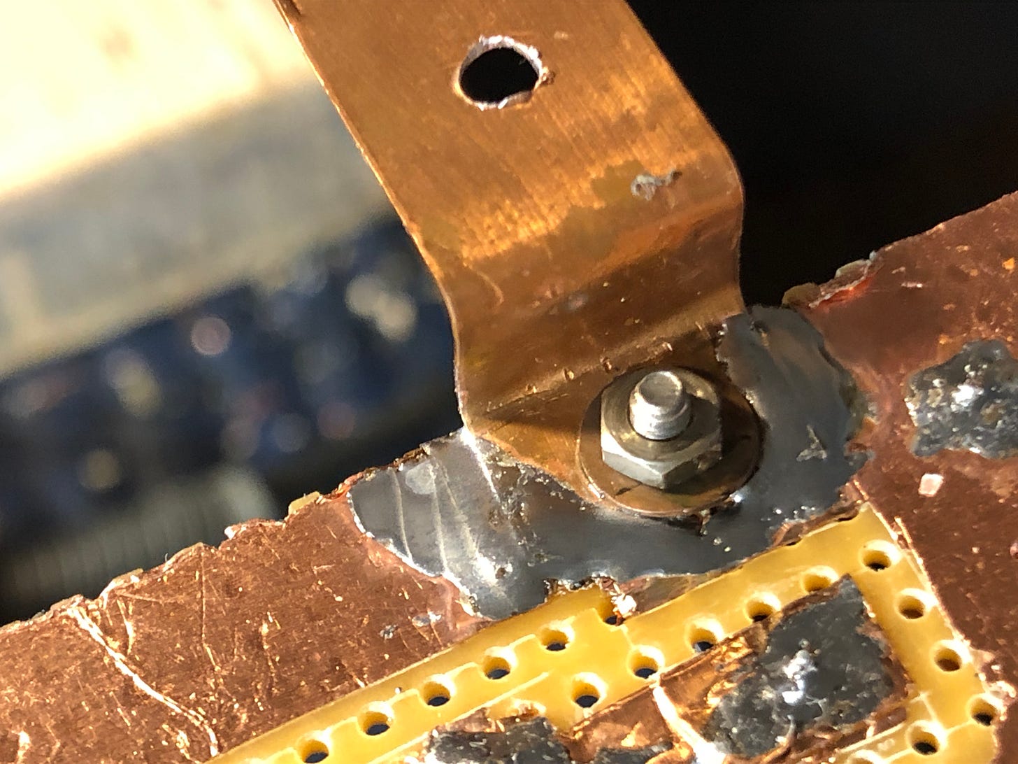
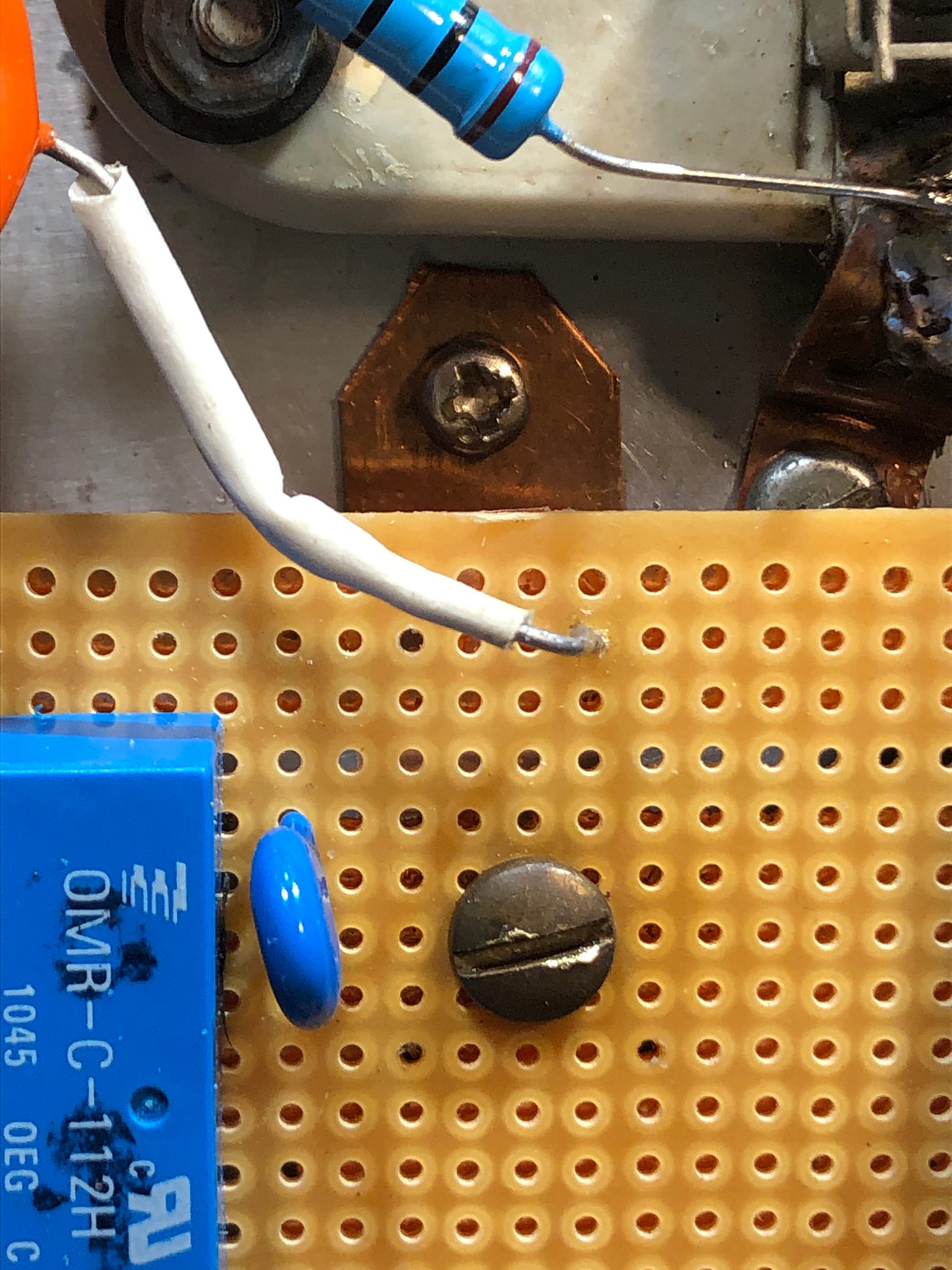
Horsing around with the production board (not detailed in this article) revealed a low-inductance RF ground had to be established between the perfboard’s ground foil and the amplififer chassis. This was accomplished by installing a few copper straps between the two, as detailed below.
One was placed near the input rail, with another near the output rail on the left side of the board. It might be necessary to add two more copper straps on the right side of the board.
Deep Dive Begins
Readers might want to get a cold beverage because things are about to get a little crazy. We are going to try to figure out how to lower the board’s SWR curves after it has been wired into the amplifier circuitry.
The first step is to discover what we have to do to the board’s components to lower its input SWR on 80 and 40 meters. This requires us to devise a means of varying the values of the fixed capacitors in the 80 and 40 meter pi circuits while the circuits are beibg swept by the NANO VNA. This enables readers to see what happens to the SWR curves when the values of these capacitors are raised and lowered.
Test Pi Circuit Jig
To do this, we construct a "Test Pi Circuit Jig". This contraption consists of an 80 metr coil installed on the prototype perfboard. Instead of installing fixed mica caps, we opt for two air variable capacitors so that their values can be adjusted while sweeping the board's SWR with the NANO VNA. This enables us to discover the fixed capacitor values needed to "redip” the SWR down to 1:1 after the board is installed into the amplifier.9
As a proviso, we should note that we added a few extra turns to the 80 meter coil causing the pi circuit to optimally perform below the 80 meter amateur band. After completing the initial tests on 3 MHz, we rewind the coil to the correct amount.
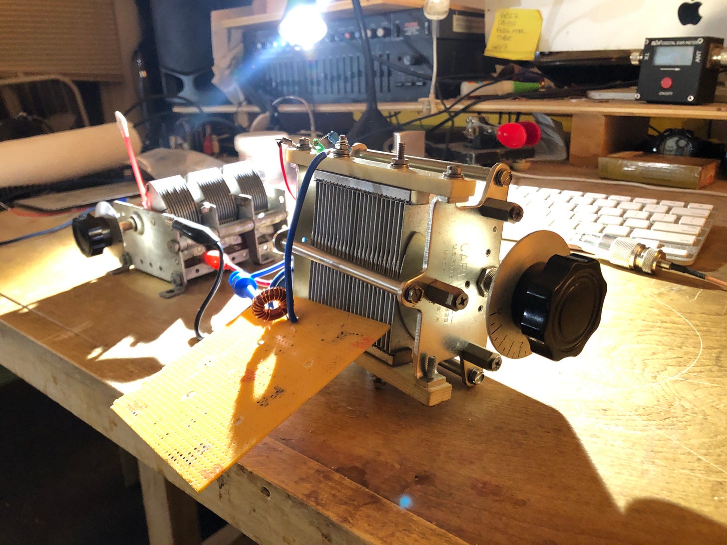
Test Jig Settings #1
We start by adjusting the air variables so that a 1:1 SWR is parked on 3 MHz, as seen below.10
When we insert a .01 coupling capacitor between the output of the pi circuit and its 50 Ohm terminating resistor—to simulate the .01 coupling capacitor in the amplifier—the SWR sweep is altered, as seen below.
Adding the .01 coupling capacitor lifts the SWR curve up as the frequency rolls off below 1 MHz. The second Test Jig sweep, above, approximates the 80 meter sweep, below, produced by the pi circuit when it was wired into the amplifier via the .01 coupling capacitor.11 So far so good.
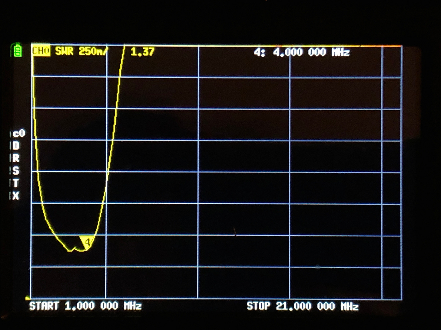
We are now at the point where we get to see what has to be done to the Test Jig to get its SWR curve back down to 1:1. This will give us an inkling of what must be done to the production board in the amplifier to get its SWR down to 1:1 on 80 meters.
For the reader’s convenience, we reproduce the second Test Jig sweep, below.
We are able to tune this sweep’s SWR minimum to 1:1 by decreasing the value of the output capacitor from 736 pfd to 614 pfd—or by about 90 pfd.
This parks the 1:1 SWR back where it was before adding the .01 coupling capacitor.
80 Meter Sweeps with Air Variables
We remove the extra turns from the 80 meter coil and resweep the pi circuit when directly terminated into 50 Ohms, and then again after it is terminated into 50 Ohms via a .01 coupling capacitor.
When directly terminated into 50 Ohms, the Test Jig exhibits a 1:1 SWR ratio on 3.8 Mhz when Cin=430 pfd and Cout=515 pfd.
We then sweep the Test Jig after it is coupled via a .01 capacitor into 50 Ohms. The 1:1 SWR ratio is parked on 3.8 MHz when Cin=430 pfd and Cout=425 pfd.
515 pfd - 425 pfd = 90 pfd
According to these sweeps, the output capacitance must be reduced by 90 pfd after the 80 meter pi circuit is coupled to 50 Ohms via the .01 ufd capacitor. This matches what we found in the 3 MHz test!
80 Meter Sweeps with Fixed Micas
We now measure the air variable values and replace them with fixed mica capacitors. When the 80 meter pi circuit is resweep, it produces the SWR curve, below.
For all practial purposes, the air variable and fixed mica sweeps are identical. This tells us the Test Jig exhibits low stray capacitance and thus can be trusted on 80 meters.
Test Jig in the Amplifier
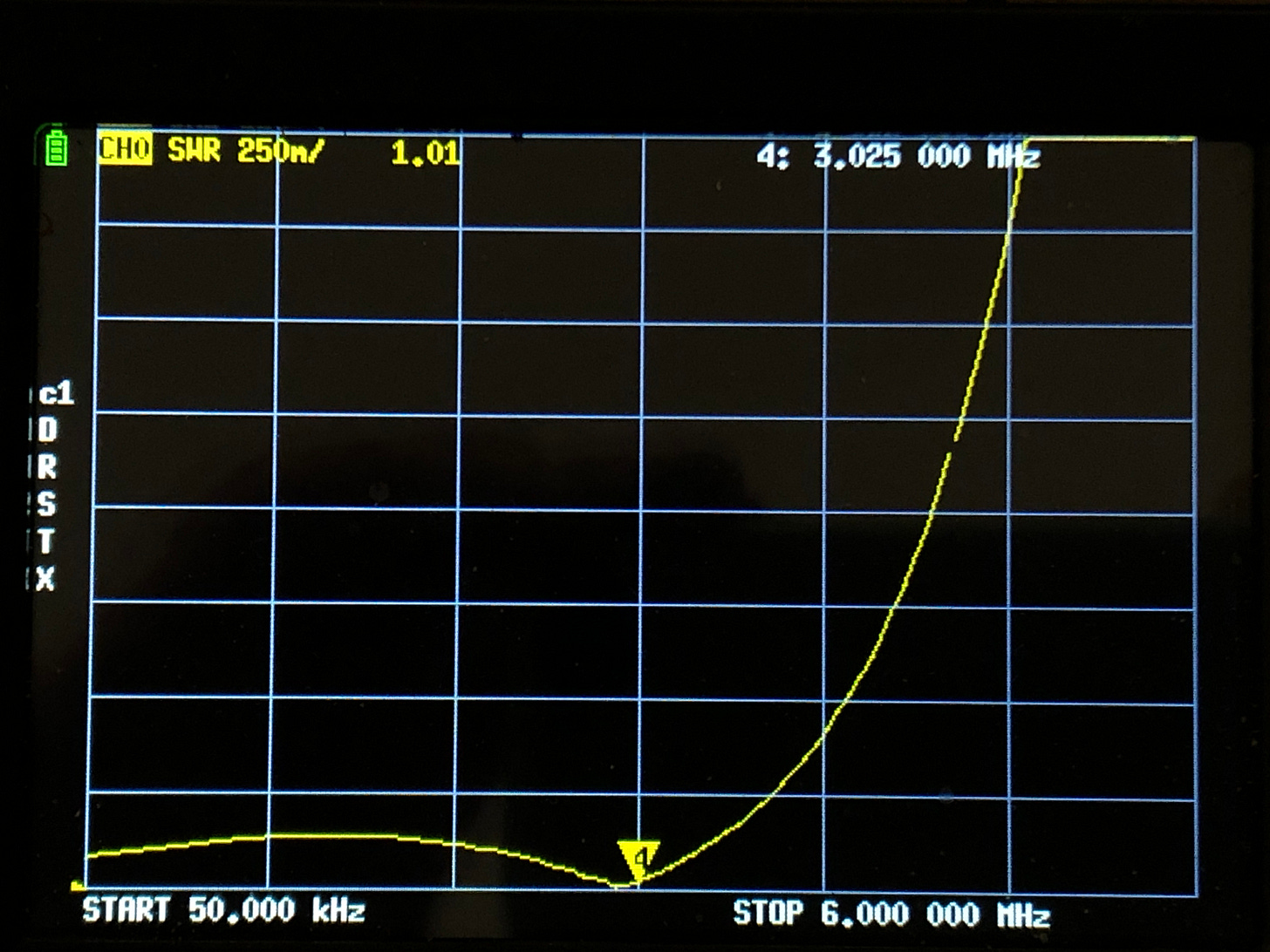
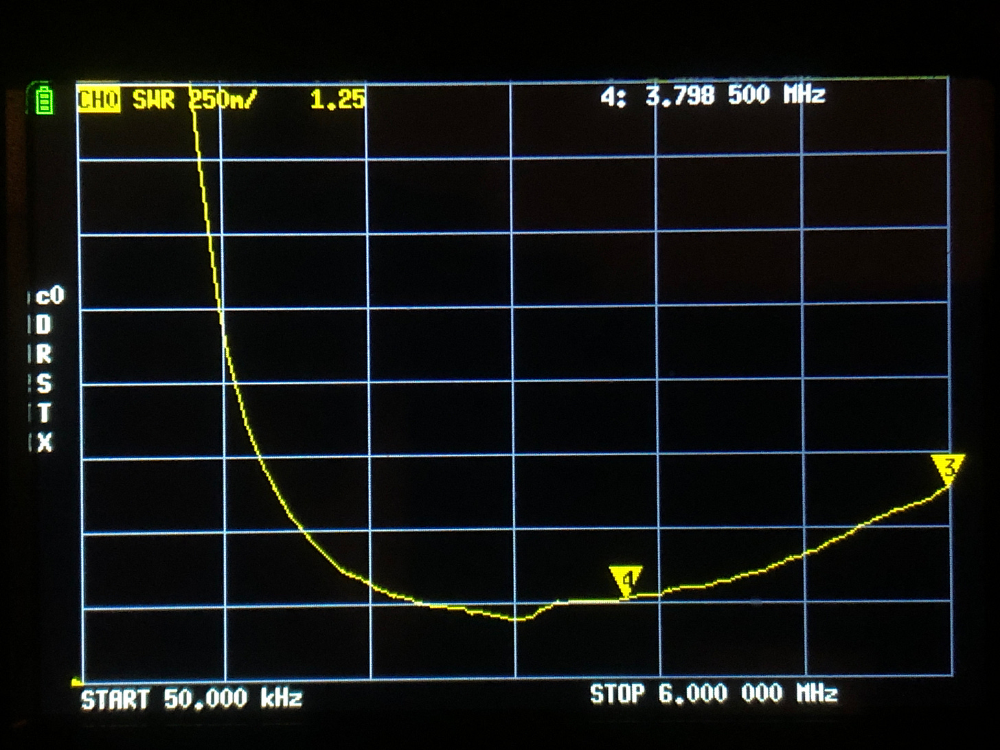
Next, we install the Test Jig into the amplifier and resweep it with the NANO VNA without the tubes in their sockets. This produces an input SWR of 1.25 to 1 on 3.8 MHz, as seen below.
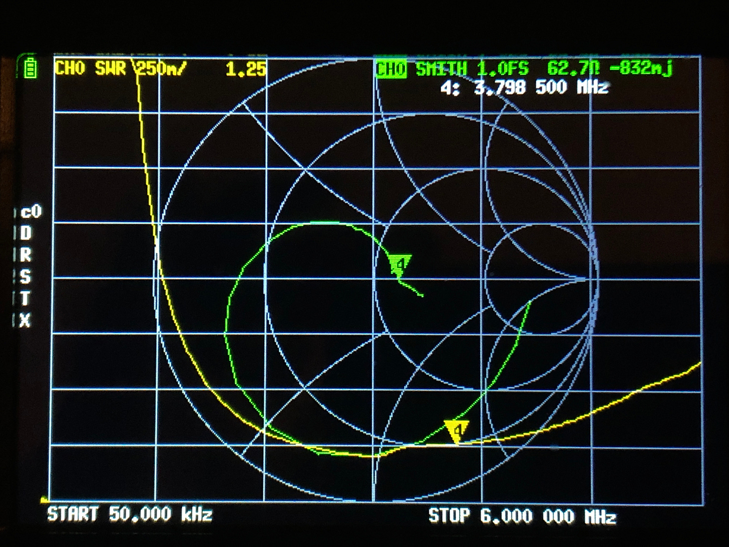
We resweep the Test Jig after installing the tubes to show readers what effect tis has on the NANO VNA sweep, as seen below.
The SWR remains the same. The Smith Chart indicates the Test Jig input is seeing an impedance of 62 Ohms with -0.8j Ohms reactance.
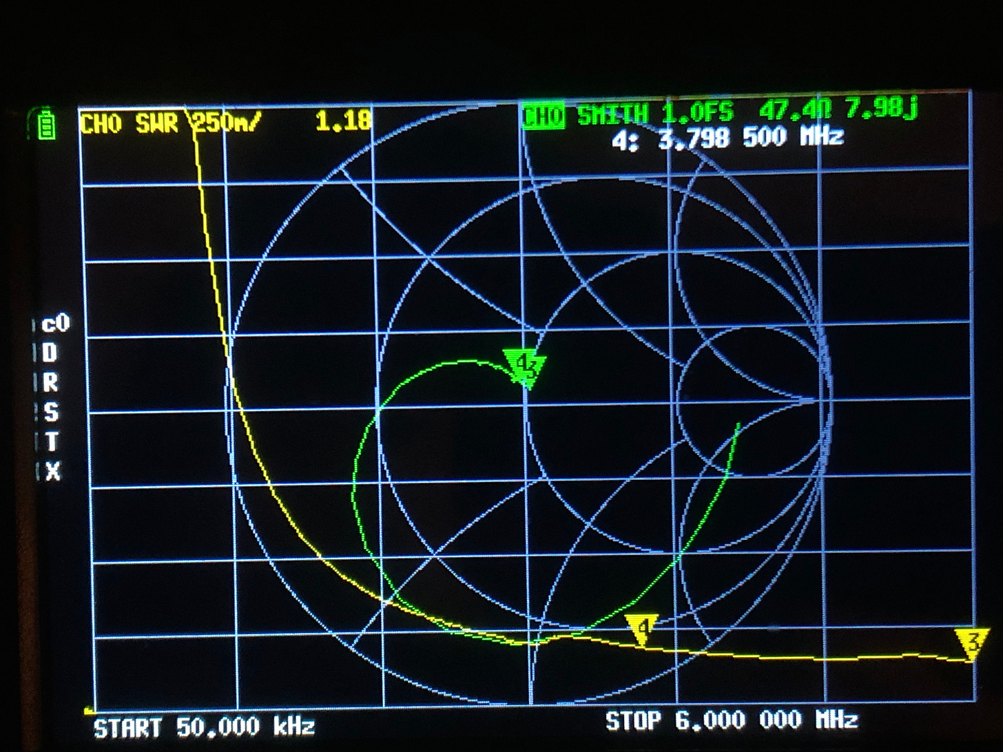
We remove the test jig and sweep the tube input via the .01 coupling capacitor to measure the load it places on the pi circuit output. This ends up being 47 Ohms with +8j Ohms reactance on 3.8 MHz, as seen below.
We don’t know why the Test Jig shows 1.25 to 1 SWR in the amplifier while showing 1.02 to 1 on the bench. But we do know this 1.25 to 1 SWR is an improvement over the 1.38 to 1 SWR exhibited by the final assembly board, reproduced for the reader’s convenience, below.
TO BE CONTINUED HERE -
INFO INSerT
SB-220 input tuned circuit component values:
80 meters: Cin = 1150 pfd | Cout = 1080 pfd | L = 2.95 uH
40 meters: Cin = 400 pfd | Cout = 470 pfd | L = 1.65 uH
20 meters: Cin = 180 pfd | Cout = 220 pfd | L = 0.93 uH
15 meters: Cin = 115 pfd | Cout = 180 pfd | L = 2.95 uH
10 meters: Cin = 022 pfd | Cout = 115 pfd | L = 0.58 uH
To match an exciter to an amplifier, it is necessary for slug-tuned coils in the amplifier’s tuned input circuit to be adjusted while the amplifier is being operated at full power.
When this is combined with the inability to adjust the input impedance of the amplifier, reduced power output can result. Tom, W8JI, provides invaluable insights about this here.
If you remove the "CB filter" from an SB-221, you need to rework its tuned input circuitry because the reactive component of the CB filter was factored into pi circuit component values.
The reverse is not true because Heathkit did not specify in the SB-221 schematic the inductance values of these coils.
The SB-221 does not use a pi circuit for 15 meters. It effectuates the match to the tubes via the reactive component within the “CB filter”, FL1. Go check out how much is being charged at this time for SB-220 input circuits.
Seams between the copper foil tape must be soldered to assure conductivity at high frequencies.
Each 110 Ohm resistor simulates the input impedance of a single 3-500Z tube. Two must be used as described, rather than a single 50 Ohm resistor tied to one of the tube’s filament pins.
At the time of writing, the 15 meter pi circuit relays had yet to be obtained from our central stash of parts.
You don’t have to use a NANO VNA to do this. A signal generator and a SWR meter works, as well as an antenna analyzer.
We wound the 80 meter coil with a few extra turns causing it to respond slightly below the 80 meter amateur band. If this Test Jig works out, we will remove the extra turns and run the experiment again on the 80 meter band.
The sweep of the pi circuit in the amplifier is conducted over a broader frequency range than that of the Test Jig. It therefore presents a “zoomed out” view of the Test Jig sweep—when the two are compared.

