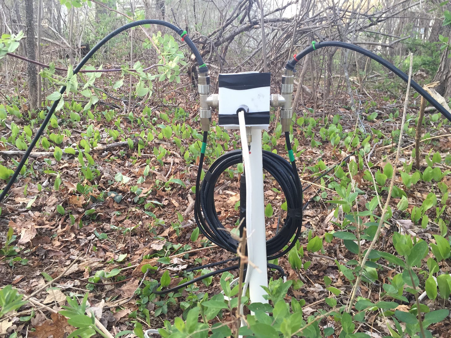
Dr. Christman’s 84º and 71º line lengths provide a straightforward means of dividing power equally between two radiators at the phase differential required for quadrature (90º) arrays.

The easiest way of obtaining Christman line lengths at various frequencies is from VA7ST’s on-line calculator, seen below. Click on its image to access it.
After calculating the line lengths, or getting them from the calculator, you have to use an electronic instrument, such as an antenna analyzer, to “prune” your coaxial cable to the precise length. This technique introduces margins of error resolved in this chapter.

Source of the Problem
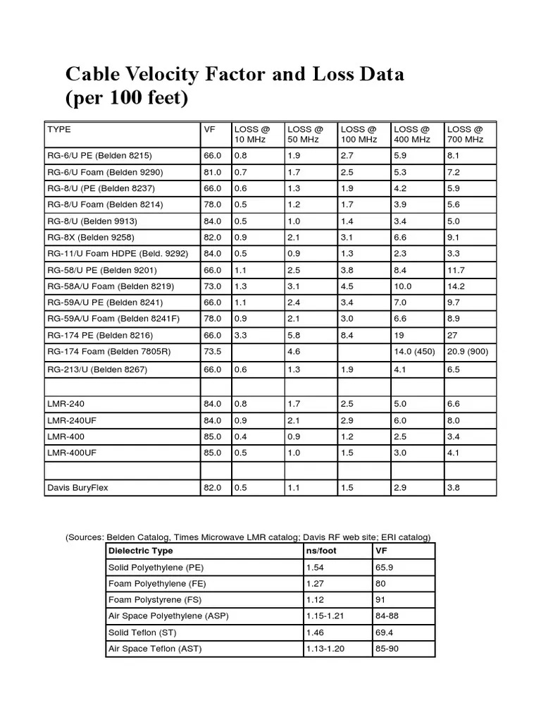
The key to the problem is your coaxial cable will have a velocity factor that differs from the one stated by its manufacturer. This slight difference is enough to throw off your Christman lines if measured with a measuring tape.1
Source of the Solution
The workaround is an old timer trick wherein a coaxial cable will, at some frequency, be 1/4 wavelength long. And when it is, an antenna analyzer will say it is shorted-circuited at one end when the other end is open. So, if we attach a Christman cable to an antenna analyzer set to its “1/4-wave” frequency, the analyzer’s R scale will read “zero” (Lo-Z) when the far end of the cable is not connected to anything (Hi-Z).
This is how we use an antenna analyzer (or similar device) to measure the lengths of Christman lines; we set the instrument to the line’s 1/4-wave frequency and snip short pieces off its end until the analyzer’s R scale reads “zero”. Easy peasy, right?
Not so fast.
Blind Spot
As things turn out, when we sweep the cable by changing the analyzer’s frequency, the R reading will go to “zero” (or a few Ohms) and stay there as we continue the frequency sweep before eventually emerging back up off its minimum or “zero” value.

Restated for clarity, there is a range of frequencies where R exhibits a minimum “zero” value. The solution is to “split the difference” by parking the analyzer’s frequency halfway between the two frequencies where R hits “zero”.2
Let’s rerack so everyone understands.

Cutting Lines with Christman
If you look at the VA7ST on-line calculator, you will see it provides frequencies where the Christman 84º & 71º lines are 90º long. These are the frequencies you want to punch into your antenna analyzer (or similar device) when snipping off the far end of the cables. We can think of these “1/4-wave” or “90º” frequencies as the “cut frequencies” for the 84º & 71º lines. So as we are snipping off the far end of a coaxial cable, we want its “cut” frequency to end up being halfway between the two frequencies where the analyzer’s R scale “hits zero”. When the “cut” frequency is parked halfway between these two “zero” point frequencies, the cable has been accurately cut by the instrument.
I am going to explain this several times to make sure all readers understand how this works. This is because tuning Christman lines is critical to getting your phased verticals to disappear into the noise when you reverse its directivity. Another is the ground system.

Explanation #1: Rocking the MFJ Frequency Knob Back and Forth
The MFJ-series of antenna analyzers use a knob to adjust frequency. Let’s say you connect a Christman line to one of these analyzers with the other end “open” (Hi-Z). Before picking up the diagonal cutters, though, you set the analyzer to the “cut” frequency and then turn its frequency knob counter-clockwise to lower its frequency. As you do so, you will see the R reading getting lower and lower until it gets no lower. This is the first “zero” point. As you continue to turn the frequency knob counter-clockwise, you will note the R reading stays at this minimum “zero” value before it rises back up. This is the second “zero” point.
Let’s say the analyzer’s R scale stays at “zero” when the frequency knob is between the 3 PM and 9 AM position. If you rock the knob back and forth between these two clock positions (while watching the R reading), you can “get a tactile feel” for where the knob is halfway between the two “zero” points. Once you get a feel for it, you park the knob where you think it is halfway between the two clock positions. In the case of 3 PM and 9 AM positions, halfway is 12 noon. Now look at the analyzer’s frequency readout. If it reads your intended “cut” frequency, you are all done. No more calls, we have a winner. You don’t need to snip anymore off the cable’s far end.3

But if it doesn’t, as will most likely be the case, you have to snip a little bit off and then rock the frequency knob back and forth between the two “zero” points. Both will have moved up in frequency because you just cut the cable shorter. So repeat the exercise by rocking the frequency knob between the two new “zero” point frequencies, intuiting where the knob is halfway between them. Park the knob at that spot and check the frequency reading. It will probably still be lower than your intended “cut” frequency, requiring you to snip a little bit more off the far end of the cable and repeat the exercise.
This goes on and on—especially if you allowed extra coax on the initial cut for safety’s sake. You’ll get anxious when you notice that the “halfway” knob position is creeping up in frequency closer and closer to your desired “cut” frequency. This means you are approaching the correct electrical length. Be careful. Keep snipping ends off the cable until the “cut” frequency is parked halfway between the two “zero point” frequencies. Try doing it without taking a Xanax.
That’s the tactile approach to using the MFJ-series of rotary frequency knobs. Next up—let’s take a look at a real world example of someone screwing up.

Explanation #2: YouTuber Botches 71º Line
To illustrate it further, examine the screenshots provided below taken from a YouTube video posted by a ham teaching others how to cut Christman lines using electrical instruments. Click on the image to watch the video.
In this case, the YouTuber is cutting a 71º line whose purple R-scale “hits zero” twice along the X-axis. We enlarge the image to see it more easily.
To the right and left the reader can see the two (purple) R-readings hitting “zero” on the X-axis. The frequency spread between them is about 500 KHz. Between them we see two vertical dotted lines. The one to the left is the YouTuber’s desired 71º “cut” frequency (4.487 MHz). The one to its right (4.600 MHz) is halfway between the two “zero” points (4.860 MHz; 3.345 MHz).
When we take a good look at this graph, we can see that two “zero” points are +/- 255 KHz from the midpoint dotted line. This tells us that the “cut” frequency is 4.600 MHz. This is not the “cut” frequency sought by the YouTuber. It’s the “cut” frequency he ends up with because he didn’t read this article!
The second dotted line—to the left of the midpoint line—is the “cut” frequency sought by the YouTuber (4.487 MHz). We see that the two “zero” points are not equidistant from it. In fact, the lower “zero” point is about 140 KHz below the intended “cut” frequency, while the upper “zero” point is 360 Khz above it! The YouTuber is way off!
How to make things right? First off—don’t focus on the “cut” frequency dotted line. Instead, focus on the two (purple) “zero” points and realize they have to be slid down in frequency until the “cut” frequency is situated halfway between them. And, of course, in order to lower the two “zero” points down in frequency coax must be added to the 71º line! Not a fun proposition because it means the YouTuber really should start over with a fresh piece of coax.4
Explanation #3: Old School Numbers Game
This explanation is for Real Hams capable of using a pen, paper and slide rule to cut Christman lines after a nuclear war. This approach eliminates the instrument’s “margin of error” by transposing the “cut” frequency to a “zero” point frequency. This scares most hams. Thus, as JFK once told RFK before stepping outside to announce RFK was the Attorney General, “Grab your balls and let’s go”.
We cut the coax longer than called for by our hand calculations. We sweep the long cable downward with the MFJ-analyzer keeping an eye out for the first “zero” point. When it appears, we write down its frequency. We continue sweeping downward until the R reading emerges off its minimum value. We write down that frequency.
We then subtract the lower frequency from the higher frequency to derive the instrument’s “error passband”. We then divide this by two (2) to determine its midpoint which tells us how far above and below our “cut” frequency the two “Zero” points need to be parked. We refer to this frequency as the “fudge-factor.”
We add the “fudge factor” to our “cut” frequency and then snip the coaxial cable shorter and shorter until the upper “Zero” point is parked on the “fudged cut” frequency.
Summation
The reason we concentrate on the two “zero” point frequencies is because the MFJ-series of analyzers accurately measure these transition points. This allows us to interpolate the “cut” frequency as being halfway between these two accurately-measured points, or “fudge” the “cut” frequency onto one of them.
Adjusting for Path Lengths
Accurate measurement of Christman line lengths must include the lengths of internal switchbox wiring, coaxial connectors and coaxial adapters in the feed system.

One path length frequently overlooked is that of commercially-available ferrite bead current chokes installed at the vertical feedpoints. You can’t just screw these things on after cutting the Christman lines. They must be connected to the coaxial cables during the pruning stage.
Confirming Christman Lines on an Oscilloscope
Readers with dual-trace oscilloscopes can literally see the amplitudes and phase relationship of the signals produced by their Christman phasing lines.
The set-up requires the feedline input connector to be excited by a signal generator on the design frequency. The 84º & (71º + 84º) lines are connected to the oscilloscope’s vertical inputs via Tee connectors terminated in 50 Ohms.

The scope sweep is then sufficiently advanced to produce two sine wave traces with the vertical inputs set to the same sensitivity.
This Textronics 465M trace shows the amplitude and phase relationship of signals produced by Christman lines excited by an HP-3525B after being tuned with an MFJ-259B in accordance with the methods presented in this chapter. The BNC-to-SO-239 adapters used in the set up are available from The Wireman ($5) here.
If you enjoyed reading this chapter of Saltwater Verticals & Phased Arrays, “grab your balls” and subscribe for $3 per month. Check out Chapter 1 here.
At least by my standards. Some people don’t care that much. Which may be why so many of the phased verticals on YouTube exhibit 15 dB to 20 dB Front-to-Back ratios.
Dealing with this “margin of error” determines whether or not your phased (vertical) array disappears into the noise when you flip its directivity away from your buddies on 40 Meters.
Well, actually you do. Nip an extra 1/4” off to compensate for the PL-259 you’re about to connect. That’s what I do.
No barrel connectors, please! They introduce loss into the Christman system, especially when used in proximity of salt water—which is the only way to fly!


