
Most antennas today are fed at a current maximum because it offers a good impedance match to 50 Ohm coaxial feedlines. But you can also feed an antenna at its voltage maximum—where it exhibits a high feedpoint impedance—with a matching network made out of a homemade coil and a scrap of coax for $25.
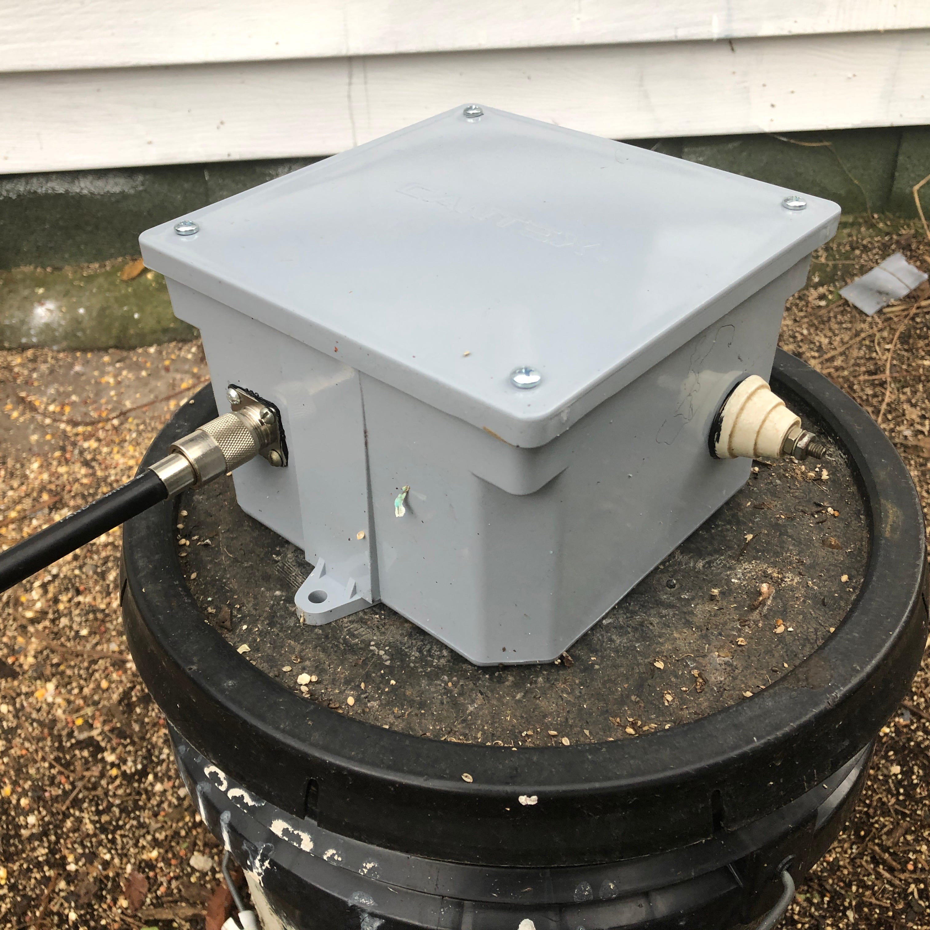
The weatherproof box is from Home Depot for about $14. The ceramic insulator is not necessary unless you use a metal enclosure. Below we see the Hi-z matching network in finished form with the coaxial feedline going back to the shack and the single HV terminal awaiting connection to the antenna.
Let’s take a look at the schematic and see how this simple thing works.

A parallel tuned circuit is connected between the antenna and earth ground. Since it offers a high impedance at resonance, this means the antenna is connected to ground via a high impedance at resonance. Which is another way of saying the antenna is not connected to the ground on its frequency of operation. And as soon as you move off the circuit’s (sharp) resonance, the antenna is connected to ground for all practical purposes—which bleeds off signals above and below the antenna’s resonant frequency.

All that needs be done is to “excite” the coil with RF energy from the transmitter. This excitation is done by connecting the 50 Ohm coax from the transmitter to a tap on the coil exhibiting a 50 Ohm impedance to ground.1 This makes the transmitter happy because it is seeing the correct load impedance. Although a variable capacitor is used to tune the contraption to resonance in the field, it is replaced with a short piece of coax exhibiting the capacitance required for resonance.
To do this we tune the contraption to resonance. Once this is done, we remove the variable capacitor and read its value with a capacitance meter. We then snip a length of coax to the length required for it to exhibit this same amount of capacitance. We then solder the shield to the low end of the coil, and the center conductor to the high end of the coil.
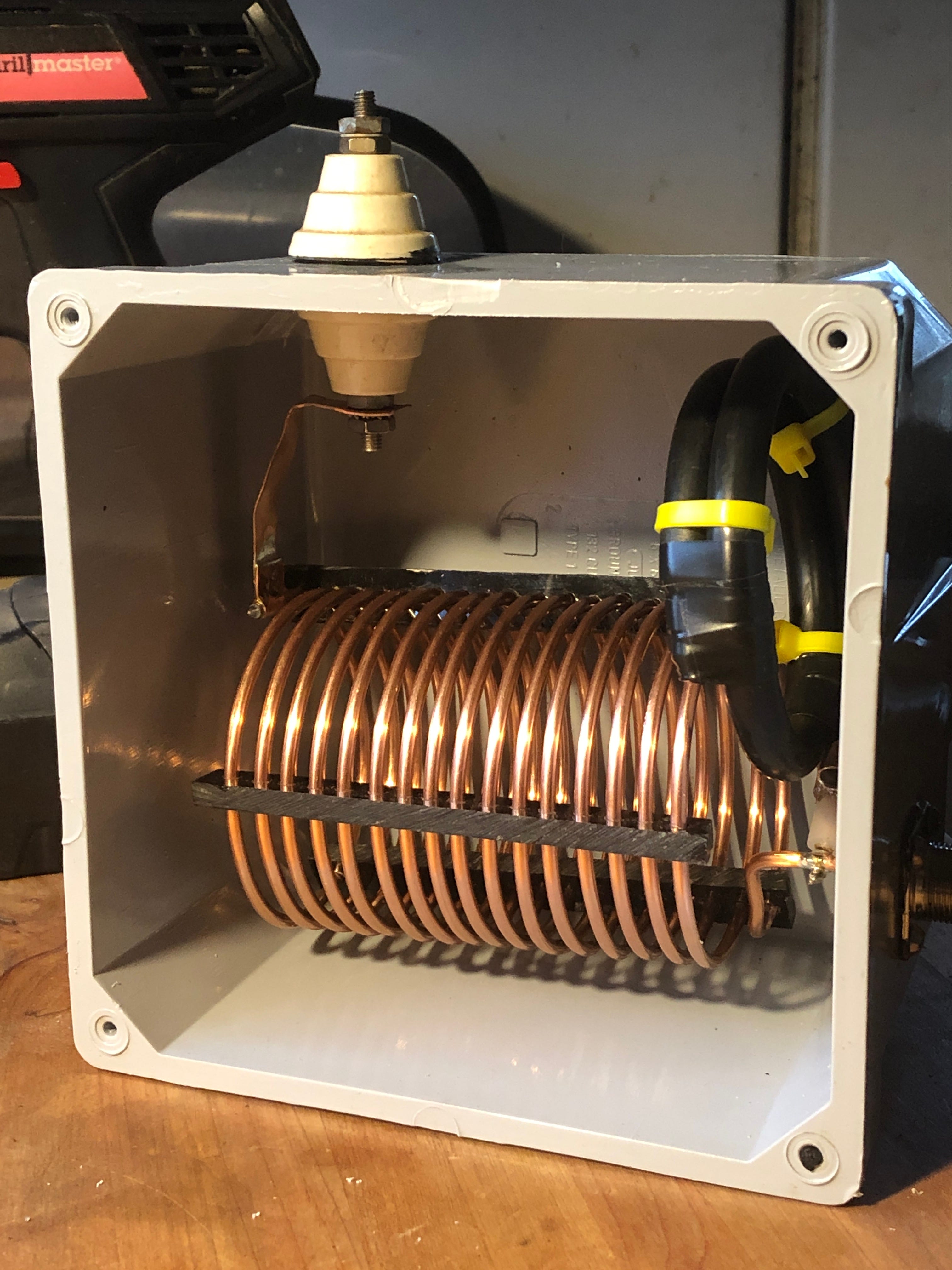
Constructing the Homemade Coil

Keep reading with a 7-day free trial
Subscribe to Saltwater Verticals & Phased Arrays to keep reading this post and get 7 days of free access to the full post archives.