Radial End-Tip Spacing
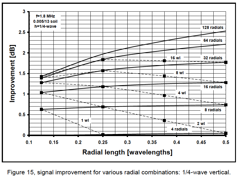
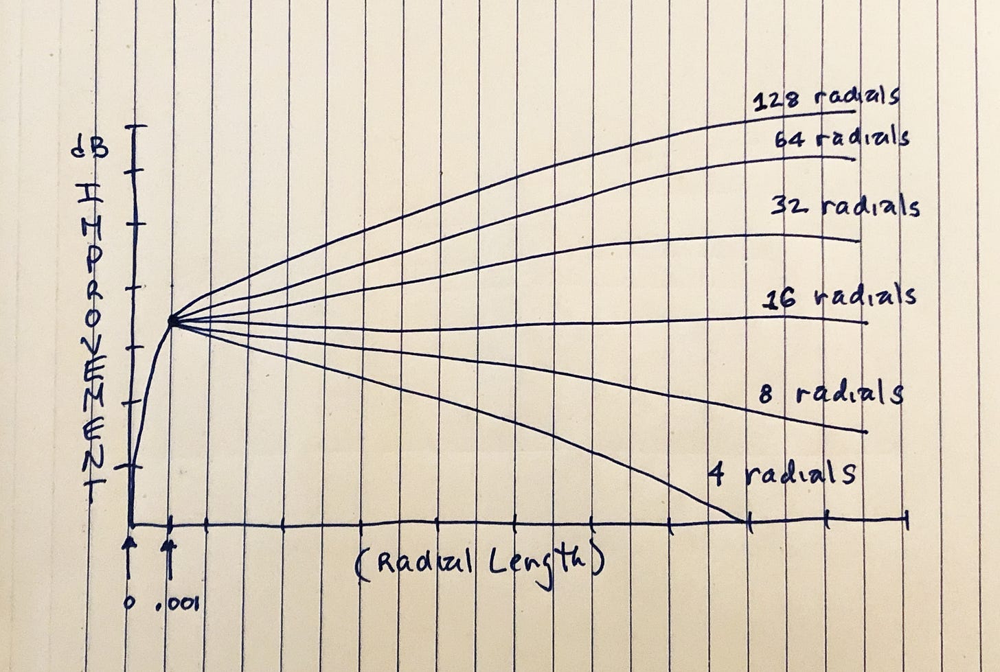
Below we see a graph produced by Rudy Severn plotting the “gain“ of a 1/4-wave vertical versus the number and length of radials in its ground system.
The takeaway is that the different curves correspond to ground systems using the numbers of radials listed below.
128
64
32
16
8
4
To simplify matters, we express the number of radials in terms of their end-tip spacing in radians.1
128 => 0.049 rad => 0.05 rad
64 => 0.0982 rad => 0.1 rad
32 => 0.1963 rad => 0.2 rad
16 => 0.3927 rad => 0.4 rad
08 => 0.7854 rad => 0.8 rad
04 => 1.5708 rad => 1.6 rad
This enables us to stop thinking about how many radials to use and start thinking about how far their ends are spaced apart.
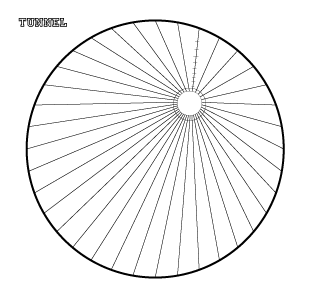
This technique helps us maximize the efficiency of ground systems installed in limited spaces where radial lengths are determined by backyard obstacles.2
A “Hybrid” Ground System
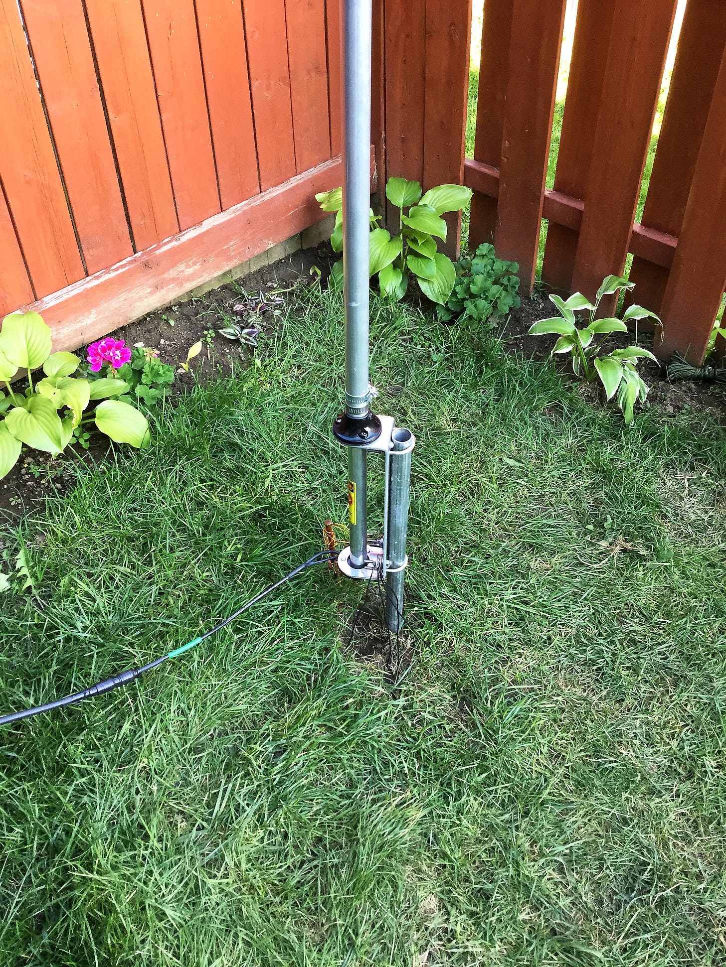
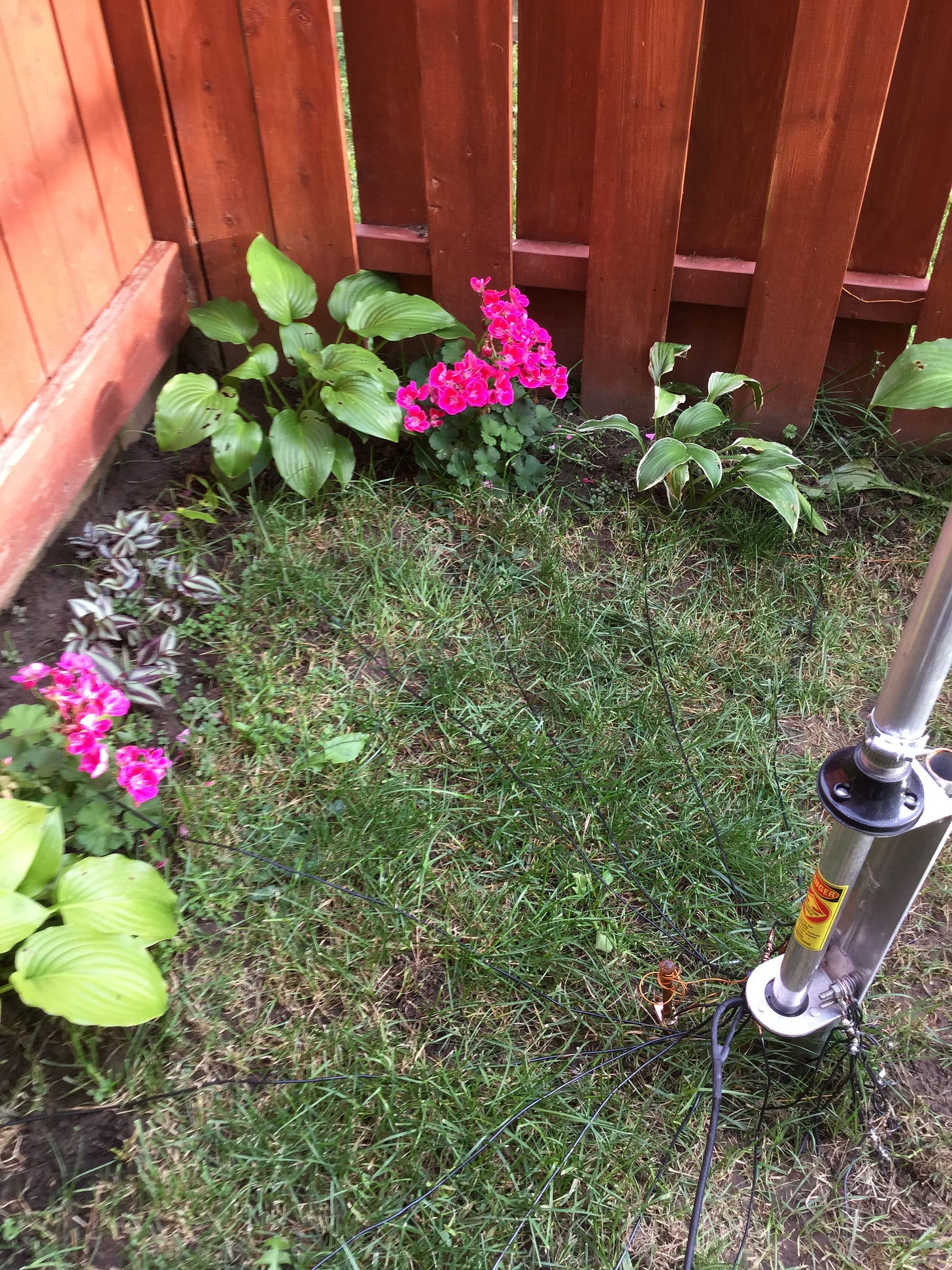
Below we see a multiband vertical mounted up against a fence in the corner of someone’s backyard. The radials extending to the fence are going to be very short. In other directions the radials will extend out much further.
If we are going to lay down a ground system in such an irregularly-shaped space, perhaps we can vary the number of radials in accordance with how far the space allows them to run. Under such conditions we would lay down more long radials than short ones in order to grab more return currents from the outermost region of an irregularly-shaped space.3
To begin the process, measure the backyard and make a drawing of it.
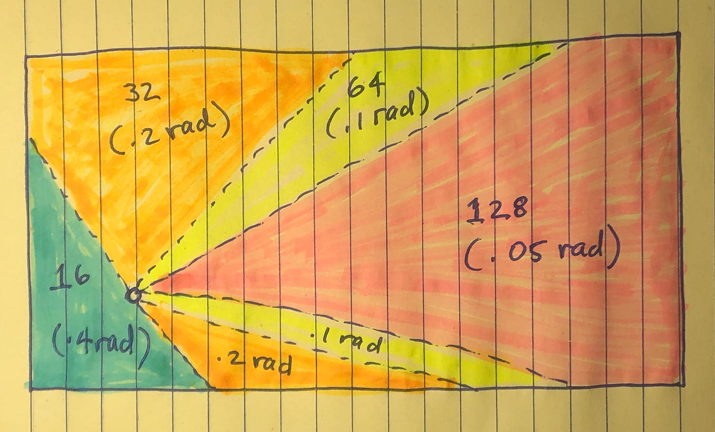
This provides a bird’s eye view of the space which we can apportion in accordance with (median) radial length runs. We then decide how many radials we want in our ground system. For the purposes of our discussion, let’s pick the 128 radial curve on Severn’s graph for maximum “gain”.
Look-Up the Radian Numbers of Each Sector
Since the “pink” sector has the longest radials, this is where we will opt for the highest (128) radial density. So we look up 128 radials in our table and see that it corresponds to an end-tip spacing of .05 rad.
Pink Sector: 128 Radial Density → .05 rad
So we lay down the first radial in the pink sector, measure it and multiply the result by .05. This tells us how far away to space the end of the next radial. Because of the irregular shape of the sector, it may come to pass that the next radial is longer or shorter than the first. Either way it doesn’t matter. We merely run the radial as far as we can, measure it, multiply that by .05 and then space the next radial that far away. We keep doing this until the sector is populated with the “long” radials.
This does not mean that we end up with 128 radials in the pink sector. What it means is that the pink sector has the same number of radials as if 128 had been laid all around the vertical.
Yellow Sector: 64 Radial Density → 0.1 rad
Next we turn to the yellow sector where radial runs are a bit shorter. We opt to lay down fewer radials—64 rather than 128. Looking up at the table we see that 64 radials corresponds to an end-tip spacing of 0.1 rad. Thus we lay down the first “yellow” radial, measure it, multiply that by 0.1 and space the next radial that far away. What this means is that the yellow sector has 64 radial coverage, again meaning its radials are spaced as far apart as if 64 had been laid around the vertical.
Orange Sector: 32 Radial Density → 0.2 rad
We move on to the orange sector where radial runs are even shorter. As the reader likely suspects, we repeat the process, but this time using only 32 radials spaced @ 0.2 rad.
Make the Job Last
If this process appears too laborious—or boring—the reader should break it up into several work sessions. Between sessions, the reader can operate the vertical to see if its performance improves while its ground system is being populated with radials. While there is a degree of satisfaction derived from this approach, it also assures that the work being performed is of the highest quality. Since 90% of installing a vertical is laying down its ground system, slow down and enjoy it for Christ’s sake!
Conclusion
Our “hybrid” ground system is optimized for 128 radial coverage.4 This means its longest radial runs are spaced as if 128 radials were installed around the base of the vertical. We could have actually laid down 128 radials, including through the shorter radial runs. But this might have pissed off the XYL while also wasting wire. So we opted to use a fewer number of shorter radials knowing it would not appreciably degrade the system’s performance. We know this to be true because that’s what Severn’s graph shows.
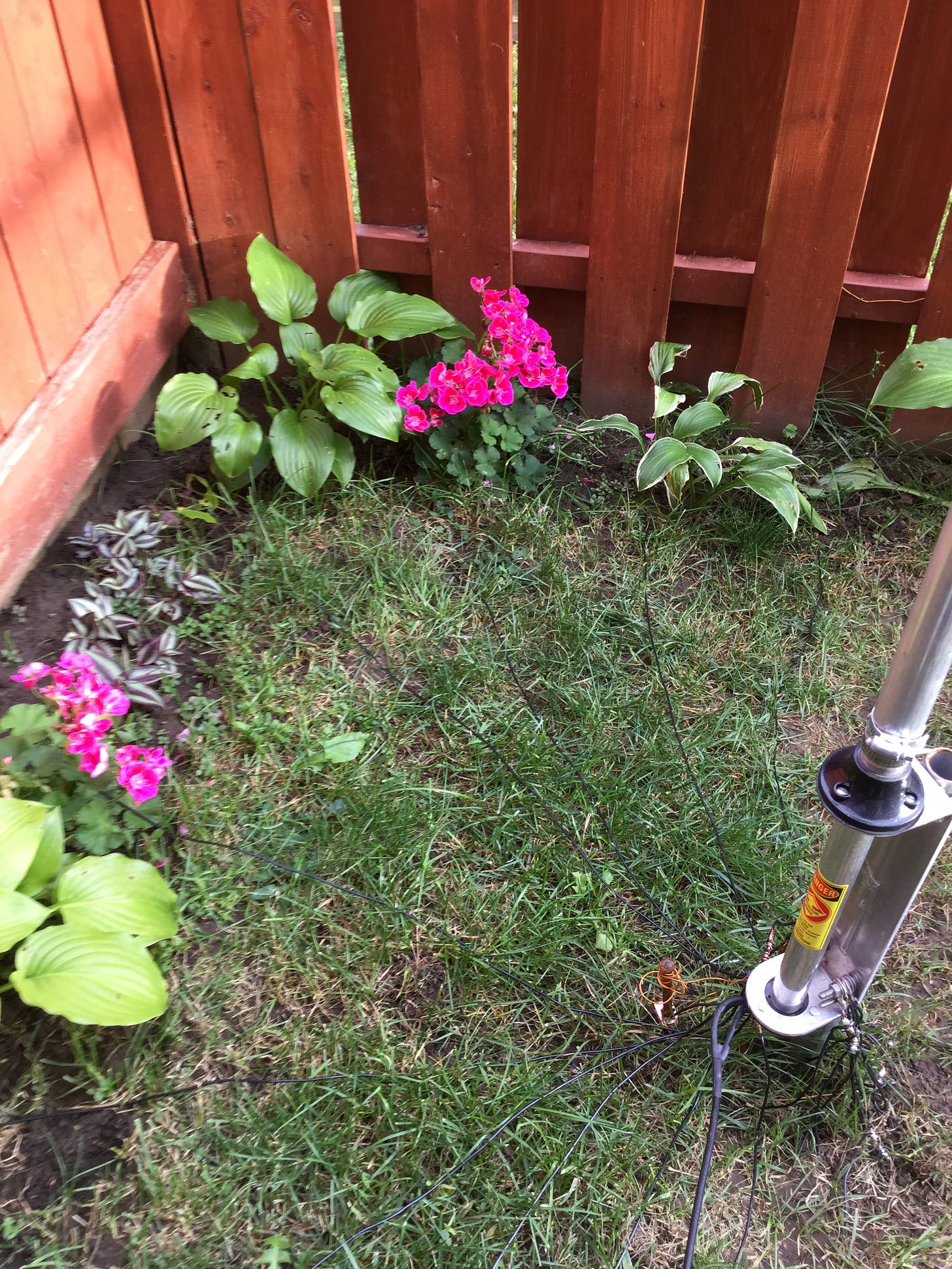
Our “hybrid” ground system does not collect as much return current as the 1937 monstrosity. It collects as much return current from this small area as the 1937 system would from this small area.
Rerack
Let’s rerack and go through ground systems again, this time for readers only interested in bare bone facts.
The Ground System Takeaway
Since sixteen (16) radials serves as the baseline of a ground system regardless of radial length, do not lay down less than sixteen (16) radials. This number of radials grabs most of the return current flowing around the base of the vertical—out to about 1/3-wavelength, according to 1937 engineers. In a limited space installation, you can cram more radials between the 16 baseline pairs on radial runs extending out longer distances. This increases the amount of return current collected at the outer region of a limited-space installation. For readers who are carpenters, think about “framing-out” the ground system “16-on-center”, so to speak. The graph below explains why.
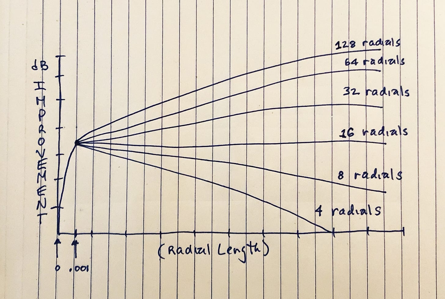
Sixteen radials produces the flat line across the graph indicating they are a “good daily driver” regardless of how far a limited space allows radials to run.5 If you are using a multiband vertical without space restrictions—lay down thirty-two (32) 1/4-wavelength radials on the lowest band of operation. Let’s now try to understand why this is true.
The Problematic Area
Because return current densities are maximized around the base of a vertical, the problematic area has always been the outermost region of the radial field—way out at the radial tips—where return currents taper off, causing them to become increasingly more difficult to collect.6
Wagon Wheel Geometry
Superimposed over this (near) field of diminishing returns is the wagon wheel geometry of the radial field, itself—giving rise to the following conundrum.
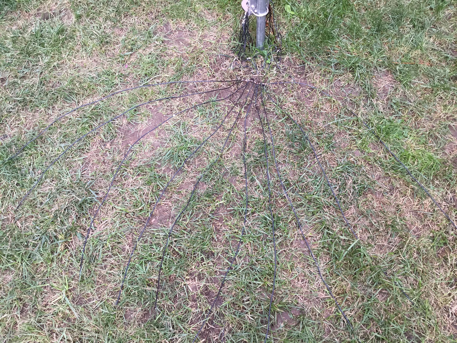
The further we progress along any radial, the further adjacent radials get away from it. Thus, given a fixed number of radials, there is a point along their lengths where the radial field could collect more return current if the radials were packed more closely together.
The conventional response to this conundrum is to add more radials to reduce their end-tip spacing in the outermost region of the radial field. If we do this, we collect more return current from the outermost region.
Supersaturatation
Whereas adding more radials increases the amount of current collected in the outer region, it does not increase the amount of current collected within the inner region where radials are spaced close enough to eliminate all ground losses. Taken in this light, the radials added to collect more return current from the outer region supersaturate the inner region with radials. In other words, we have “too many radials” in the inner region of the field, which many consider being a “waste of money”.
The Compromise of 1937
This trade-off between the number vs length of ground radials has been a source of contention amongst amateurs for decades—despite the fact that radio pioneers settled the matter in 1937 when stipulating the “optimum” radial field as one hundred twenty (120) 1/2-wave radials. FCC and American Radio Relay League officials subsequently endorsed this finding thus settling the matter. Sort of.
The Faux Debate
But then hams with all of the space in the world, who were nevertheless cheapskates, started complaining about how much money 120 radials cost, thus re-triggering the “number vs length” debate. This debate rages on today and has always been about economizing wire expenditures in amateur ground systems unencumbered by space limitations, as demonstrated below.
The “number vs length” Debate
Below is a passage from RadioEnthusiast written in 2018 by PJ2DX “dispelling some myths” about optimizing ground radial systems. The bold text is mostly mine for emphasis.
How Long? — There's an old maxim that says given a particular amount of wire it's better to put down many short radials than fewer long ones. The 1937 paper states that radials should be 0.5l long but what if you only have enough wire available to put down, say, four 0.5l-long radials? Wouldn't eight 0.25l-long radials therefore be better? What about sixteen 0.125l-long radials? The answer in both cases is “yes”: radials need only be as long as 0.5l if you are putting down as many as 120 of them.
If you have put up a quarter-wave vertical with a few 0.25l radials buried or lying on the ground, you could probably improve its performance by shortening the radials and adding more of them – read on!
This raises another question and that is “how short can radials be and yet still be effective?” John Stanley K4ERO did some work over 40 years ago in order to answer that question. Summarising (sic) data contained in a professional publication, Radio Broadcast Ground Systems, Stanley wrote an article in the December 1976 ARRL magazine QST. His work is quoted in The ARRL Antenna Book [2] and Table 1 is an extract of data presented there which in turn was derived from information in Radio Broadcast Ground Systems.
This table actually provides us with a great deal of information, not least the all-important relationship between “how many?” and “how long?” and the findings are somewhat counterintuitive (sic). For example, the fewer radials you put down, the shorter they can be…
Table 1 shows that if you only put down 16 radials, they need be no longer than 0.1l. You could make them longer than that but – with only 16 – performance wouldn't be improved by increasing their length: you would also need to increase their number.
As the amateur ‘standard’ is 0.25l-long radials, what if you have already put down sixteen 0.25l-long radials on the ground? You could expect to improve your signal by about 1.25dB if, instead, you put down 30 radials each 0.13l long.
Below is another sample of this economic debate.
Fixed Amount of Wire
Because this debate is predicated on the most economical use of wire in a ground system, amateurs unaware of this fact presume it to be a scientific debate. Articles in ham magazines discussing “number vs length” thus merely advise readers how to get the “biggest economical bang” out of their ground radial buck, and rarely figure space limitations into such discussions about optimizing ground radial systems.7 In fact, Rudy Severn, in his chart, above, fails to consider distances to the vertical less than .1 wavelength8 by failing to plot his “number vs length” curves down that far. Apparently, hams dealing with limited spaces are furthest from the minds of those engaging in the “number vs length” economic debate.
Analyzing the Charts
When we extend Severn’s chart in the childishly drawn diagram, above, we see “number vs length” curves converging at distances regularly encountered in limited space installations. Whereas 16 radials appear to provide a decent baseline of “gain” regardless of radial length, more than 16 increases the collection of return current at distances from the vertical frequently not encountered in limited space installations. Since all radials physically converge at the vertical’s base, Severn’s “number vs length” terms also converge since they collect increasingly equal amounts of current the closer they get to the vertical’s base.9
Optimizing Wire in Limited Space Ground Systems
In limited spaces, radial lengths are determined by backyard obstacles. This eliminates length as an attribute that can be tweaked to optimize wire use. The only thing left is the number of radials. The takeaway is to vary the number of radials in accordance with how long they are. The longer the radial, the more we want to lay down. This reduces their end-tip spacing which, in turn, maximizes the collection of return currents from the outermost regions of the irregularly-shaped radial field.
Recap
The idea of not bothering with radials shorter than 1/4-wavelength is a common reason why many backyard verticals do not work very well. To correct this situation, we want to lay down lots of long radials in order to reduce their end-tip spacing so that they collect as much return current as they can from the outermost regions of the backyard radial field.
Let’s have some fun with math and derive the end-tip spacings of radial fields on different amateur bands through two means.
Calculating End-tip Spacings
Because the perimeter of a ground radial system is its circumference, we can calculate its length with the equation used to determine the circumference of a circle.
C = 2πR
The circumference of a circle is equal to 2π times its radius. In the case of ground radial systems, the radius term is the radial length. Since the 1937 “ideal” system uses 1/2-wavelength radials, let’s calculate its circumference on several HF bands, as seen below.
C=2πR
C = 6.28 x 1/2-wavelength = 3.14 x wavelength
1937 “Ideal” Perimeter (using 1/2-wave radials):
160 Meters => 1,648’
80 Meters => 824’
40 Meters => 412’
20 Meters => 206’
15 Meters => 154’
10 Meters => 103’
Since we know that the 1937 system used 120 radials, we can divide these perimeters by 120 to find out how far apart the 1/2-wavelength radials are spaced apart from one another on the different amateur bands.
C/120 = End Tip Spacing
1937 “Ideal” Radial Tip Spacing (1/2-Wavelength Radials)
160 Meters => 1,648’/120 = 13.7’
80 Meters => 824’/120 = 6.83’
40 Meters => 412’/120 = 3.42’
20 Meters => 206’/120 = 1.72’
15 Meters => 154’/120 = 1.28’
10 Meters => 103’/120 = 0.86’
Let’s double-check that by using the radian method described at the beginning of this chapter. To make this easier, we reproduce the radian table, below.
128 => 0.049 rad => 0.05 rad
64 => 0.0982 rad => 0.1 rad
32 => 0.1963 rad => 0.2 rad
16 => 0.3927 rad => 0.4 rad
08 => 0.7854 rad => 0.8 rad
04 => 1.5708 rad => 1.6 rad
According the table, 128 radials corresponds to “.05 rad”. So we have to figure out how long a 1/2-wavelength radial is on the different amateur bands, and then multiply this by .05 rad to resolve the end-tip spacings. Let’s do this for 160 Meters longhand, and then repeat it for the other bands.
160 meters / 2 = 80 meters
80 meters x 3.28 feet/meter = 262.4’
262.4’ x .05 rad = 13.12’
13.12’ is pretty close to the 13.7’ end-tip spacing on 160 Meters we calculated using the first method. The reason the two spacings are not precisely equal is because the 1937 system calls for 120 radials whereas we used 128 in the radian measurement. It’s also due to the difference between an arc and a straight line subtended by the same angle, best relegated to a footnote.10
When we run the calculation for the other bands, we get the following results (parenthesis conveys end-tip spacing from the first calculation).
End-Tip Spacing: Radian Method (128 Radials)
160 Meters => 13.12’ (13.7’)
80 Meters => 6.56’ (6.83’)
40 Meters => 3.28’ (3.42’)
20 Meters => 1.64’ (1.72’)
15 Meters => 1.23’ (1.28’)
10 Meters => 0.82’ (0.86’)
We can see the two ways of calculating 1937 end-tip spacings produce pretty similar results.
Let’s now calculate the end-tip spacing for radials of varous lengths commonly encountered in backyard installations. The radian method resolves the following values for 128 radials.
Spacings of 128 Radials of Different Lengths (Radian method)
50’ => 2.6’
40’ => 2’
30’ => 1.6’
20’ => 1’
10’ => 0.5’
5’ => 0.26’
2’ => 0.1’
Readers can use these figures to ballpark how far apart to space radials of varying lengths when installing their ground system in an irregularly-shaped backyard. Remember, these spacings are for ground systems using 128 radials. Doubling the spacing reduces the radial number in half.
What this means is that if you can run radials in your backyard 20’ or so, don’t think about how many to run. Merely run the first radial and then lay the next one alongside it and anchor it 1’ from the first radial. Then, if you can run radials in another direction about 40’ or so, run the first one and then run the next, anchoring its end 2’ from the first.
Conclusion
Installing a ground system is fun when you know it maximizes the collection of return currents from an irregularly-shaped, backyard space. Vary the number of radials in accordance with their length. Take your time by breaking the installation up into several sessions. After completing a session get on the radio and ask hams for signal reports so you can document what happens as you build out your ground radial system.
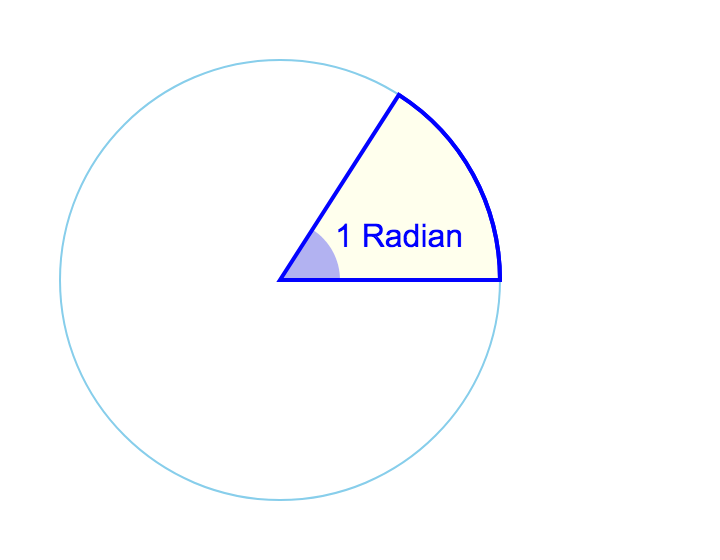
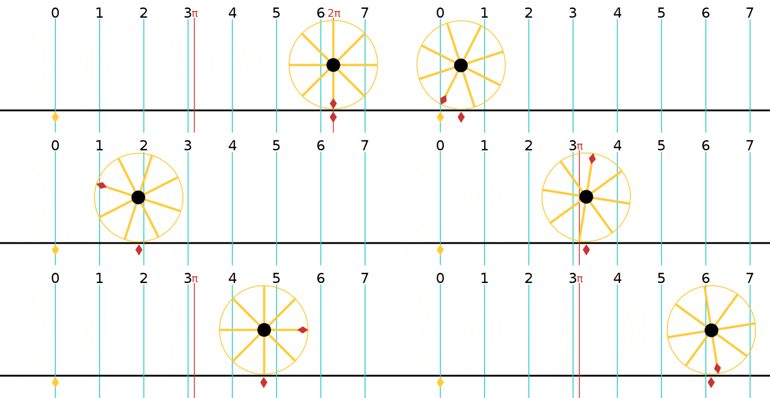
A radian is what happens when you take the radius of a circle and lay it down along the circle’s perimeter, as if it was a piece of string.
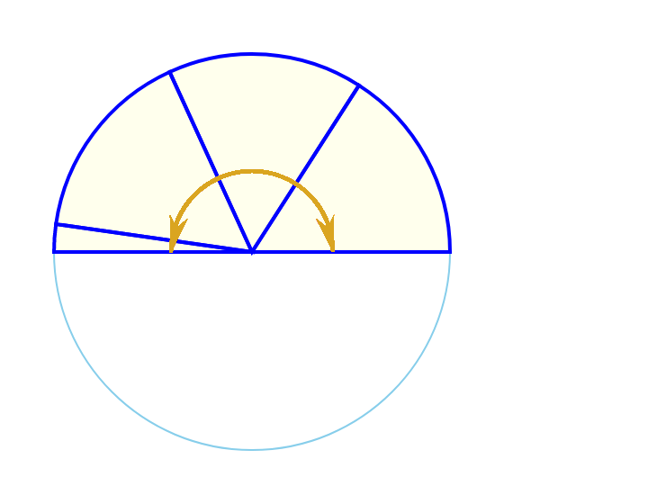
However far it goes, the angle it forms at the center of the circle is 1 Radian (about 57º). Radians are a way of expressing the size of an angle without using degrees (º). If you keep doing this along the perimeter of the circle, it turns out you can lay 3.14 of them—or π of them—along half the circle, which is 180º. And 2π of them (6.28) around the while circle.
It’s no coincidence that the equation to figure out the circumference of the circle is “two π times the radius”.
C = 2πR
Which can also be read that as “two π radians”. Get it?
In simple terms, radians can be thought of as the length of crust on a slice of pizza. By knowing how long the crust is, you know the angle of the pizza slice in radians.
SIDENOTE: the words “radius”, “radial” and “radian” are similar—with “radian” &“radial” differing by but one (1) letter. Maybe that means they have something to do with one another… 8D
Decide how many radials you want. Look up the corresponding radian number in the accompanying table. Lay down the first radial. Multiply its length by the radian number provided in the table. Space the next radial’s tip that far away. Keep doing this calculation when laying radials around the vertical.
This maximizes the return current we collect from the limited space, which, in turn, maximizes the vertical’s radiation efficiency. This, in turn, maximizes the amount of power our vertical ends up emitting into the “ether”. 90% efficiency and above are commonly achieved through meticulous tuning, as described in an upcoming chapter.
We acknowledge our hybrid system collects less return current than would be the case if we had laid out 128 radials regardless of length. But the difference is so small that it does not warrant reference other than to head off internet trolls.
Don’t shy away from banging on your neighbor’s door with a six-pack asking if you can staple some wires into their back lawn coming from underneath your fence. You gotta ask.
1937 engineers say this extends out to 1/3-wavelength, after which currents drop off precipitously regardless of a ground-mounted vertical’s height (length).
This is because the discussion is about how to optimize ground radial systems economically, not scientifically.
That’s 32 feet on 80 Meters; 16 feet on 40 Meters; 8 feet on 20 Meters, etc.
And thus the number of them does not matter as much as it does the further out one progresses into the outer regions of the radial field.
This is for the footnote where we do the mathematical calculations showing the difference between an arc subtended by an angle versus a straight line between its end points. I have to circle back to this at some point in the not-too-distant future. 8D.


