After restoring a 1960’s muscle car, its hard not to push the pedal to the metal to see fast it can go. Same thing holds true with a pair of phased verticals over saltwater. But in this case, the temptation is to check the array’s performance at extremely low elevation angles (ELEA)—say, below 5º—where the “rubber meets the road” as far as DXing is concerned. How do we do that?
A Marathon
One way might be to see how long a pair of saltwater verticals on 7 MHz can maintain a signal into Europe after daybreak. From the East Coast this would mean either a double 8º hop, or a single-hop extended by ionospheric tilting. We find the second prospect most enticing.
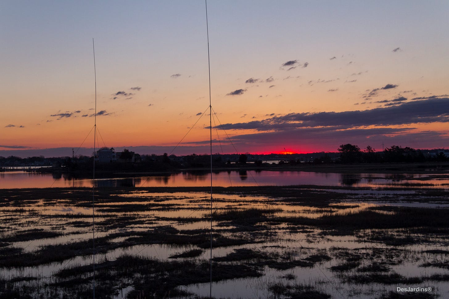
The ELEA Experiment
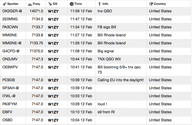
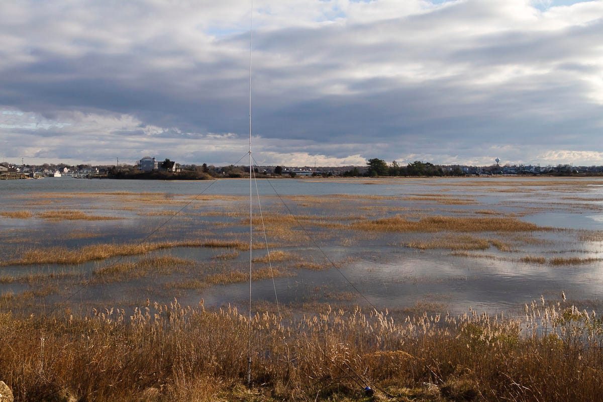
On the morning of February 12, 2019, this was attempted from the salt marsh behind Cap’n Jack’s Restaurant in East Matunuck, R.I. The results? A signal was maintained in Europe past high noon, Central European Time.
One Way Propagation
Unexpectedly, UK & European signals could not be heard on the phased verticals in Rhode Island. This required use of a remote receiver in the UK to work them. In the audio recording, below, we hear the initial ELEA call to Europe on the remote receiver at 9:45 AM local UK time.
So what’s happening here? Did our signal make it to the UK in one or two hops?
Background Briefing
In Chapter 1, we learned that the ionosphere “tilts” within the earth’s day/night terminator, affording radio signals a varying index of refraction at the beginning and end of chordal hop propagation.
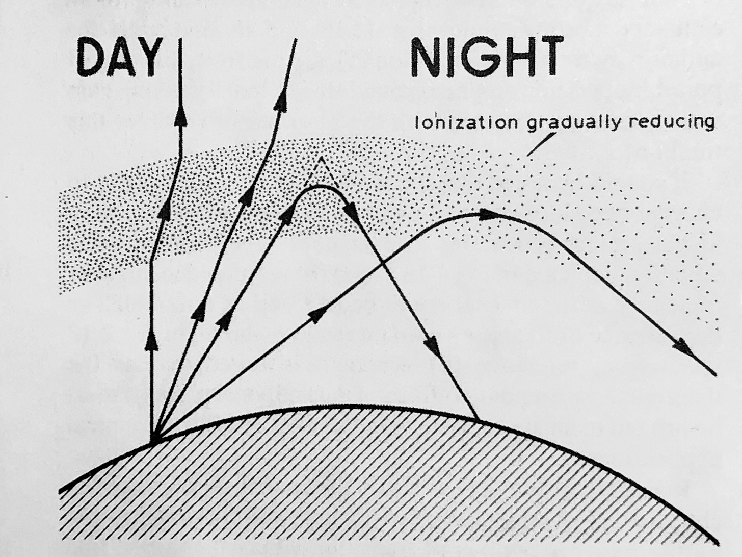
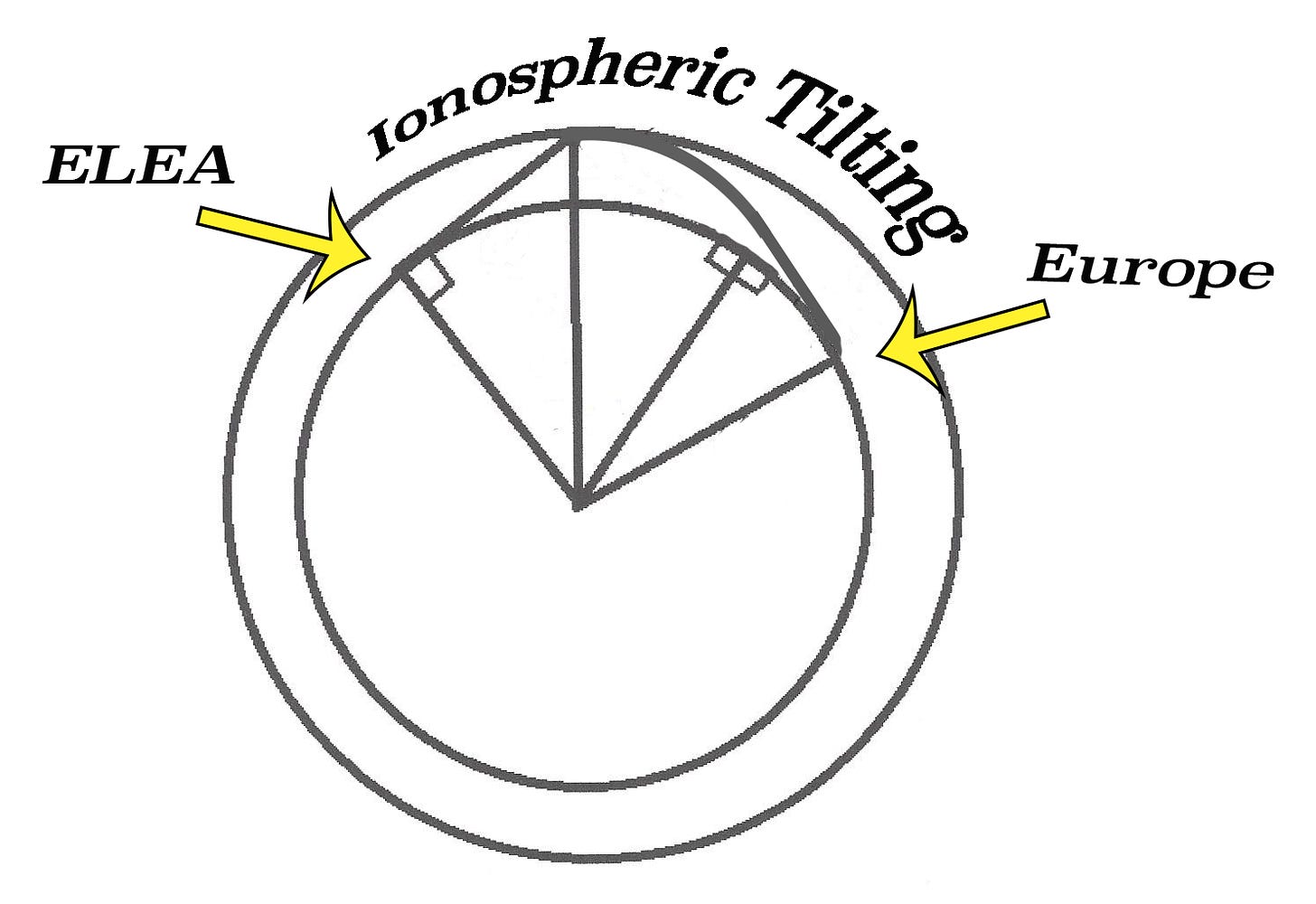
The ELEA experiment proposes to inject a signal within this “tilted” region of the ionosphere at an acute angle to see if its first-hop is elongated all the way to Europe, as fantasized below.
Chordal hop propagation ends when the signal reemerges back into daylight where increasing ionization gradually refracts it back down to the ground. In the recording below, we listen in Europe to the ELEA signal communicating with a station in the Netherlands at noon, Central European Time. Note its lack of QSB and selective fading. Does this mean the signal crossed the Atlantic in a single hop?
Test Preparations
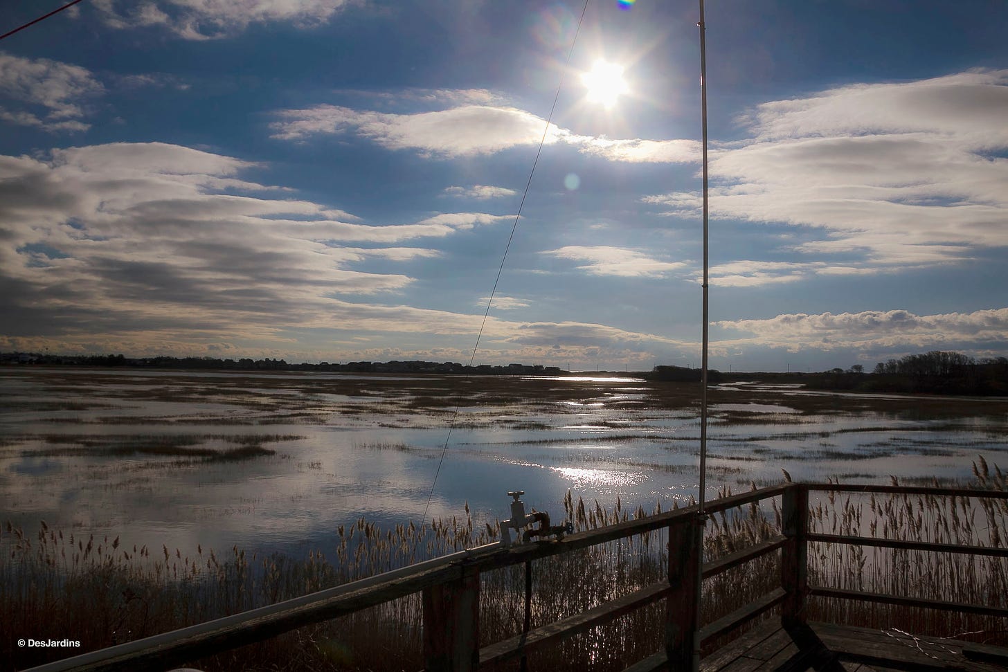
To prepare for the test, we attempted to energize Succotash Salt Marsh so that its surface would act as a ground plane extending out into the array’s far field. This was undertaken to maximize the aerial’s emissions just above its pseudo-Brewster Angle (which is about 0.5º on 7 MHz over saltwater).1 A brief review of the "Skin Effect" helps us understand.
The “Skin Effect”
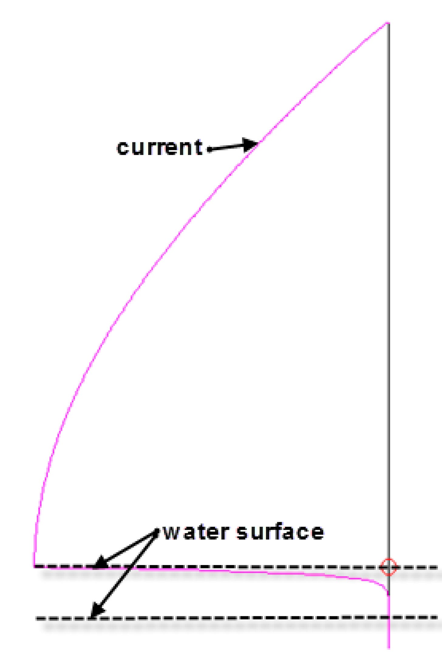
Just as RF energy flows along the outer surface of a copper wire, this “Skin Effect” also applies to ground systems under vertical radiators installed over salt water—according to an article by Rudy Severns available here.
Return currents sought by a saltwater vertical's ground system flow along the water’s surface. The deeper one penetrates into the water column, the lower the flow of these currents. At 7 MHz, the salt water “Skin Effect” extends down about 3”. Below this depth, less than 37% of surface return currents are still found flowing.2
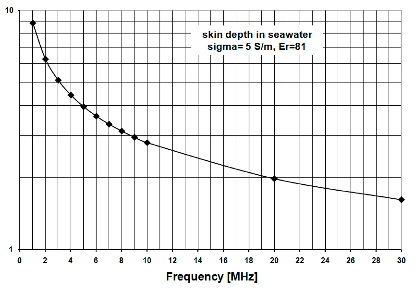
This would seem to suggest that radials on 7 MHz should be immersed no deeper than 3” into salt water in order to maximize a vertical’s radiation efficiency. Although the surface of a salt marsh is frequently mirror smooth, its depth varies in accordance with the sinusoidal pattern of the moon’s orbital influence on ocean tides. In Succotash Salt Marsh, average high tides immerse the marsh floor under 2 feet of salt water. There were, of course, exceptions.
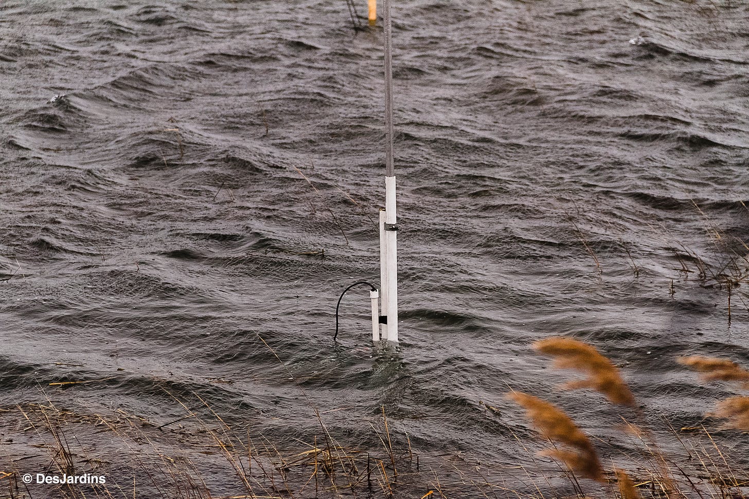
Some method needs to be engineered to enable ground radials to be submerged no more than 3” into this varying water depth.
Reconfiguring Radial Wires to Harness the Skin Effect
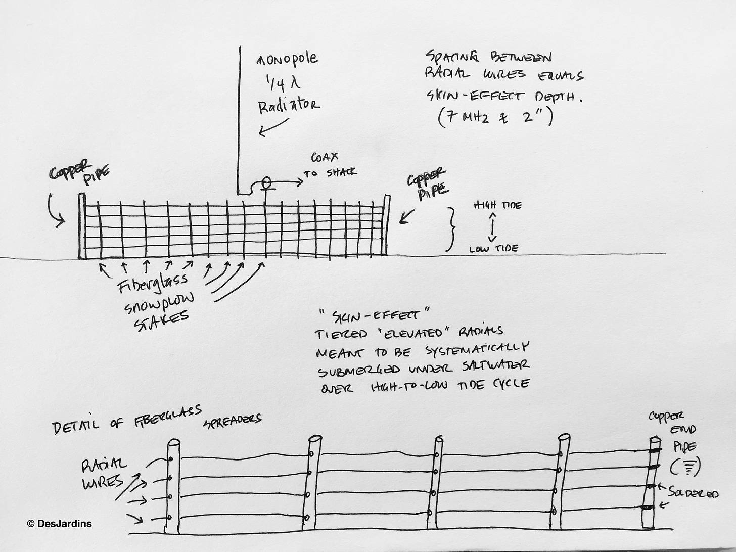
The 25 radials under each vertical were divided into 3 groups elevated at different heights above the marsh floor so that any one group would be submerged less than 3” under salt water at high tide. This was the best we could do given the limitations of our operation in the tidal salt marsh.
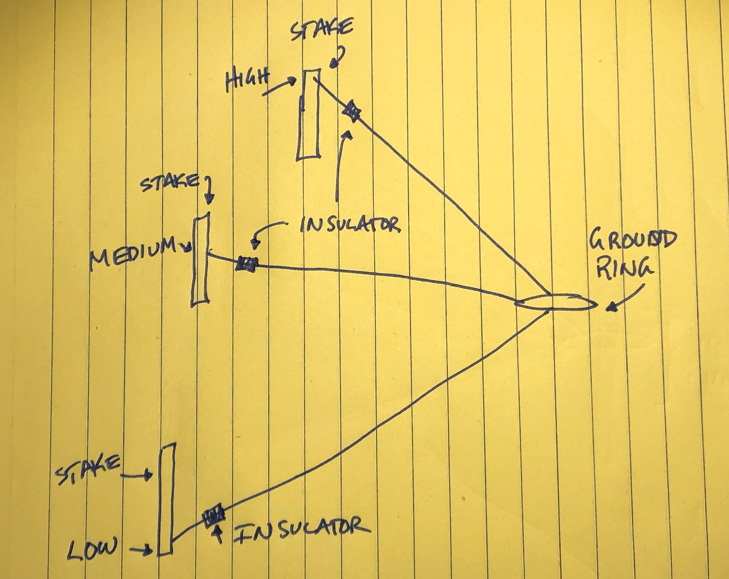
The three groups of radials were tied off at three different heights along stakes driven into the muck around the array’s perimeter. The center ground rings under the vertical radiators were elevated above mean high tide. After several days of experimental transmissions—including one to South America, heard below3—the stakes were removed to lessen visual impact, causing all radials to slope at the same angle into the water’s surface.
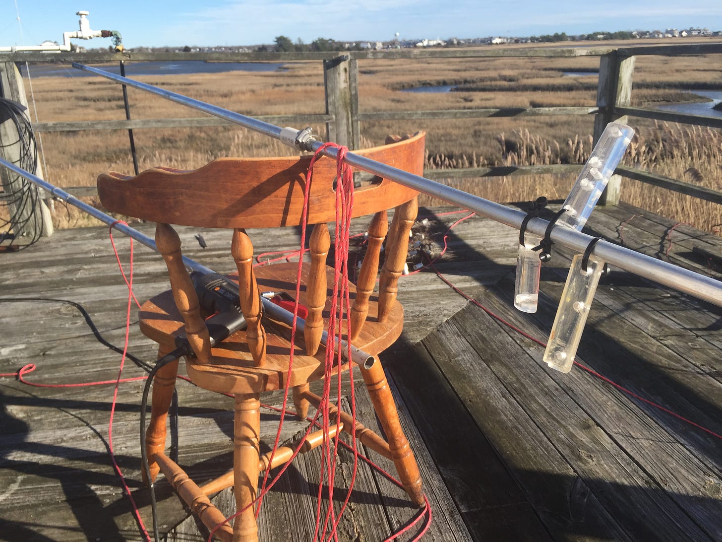
Another approach, seen below, resembles an "electric fence". Two such contraptions installed perpendicular to one another might suffice for DXpeditions using a multiband vertical over a tidal lagoon.
Previous Experience with Saltwater Ground Systems
Our attempt to “energize” the surface of Succotash Salt Marsh was assisted by experiments conducted when initially setting up the verticals which merit detailed review.
In the Beginning
On the first day of operation, a vertical was installed on the rear deck of the house provided by Cap’n Jack’s restaurant. Its ground system consisted of a few radials haphazardly thrown into the marsh reeds at sunset.
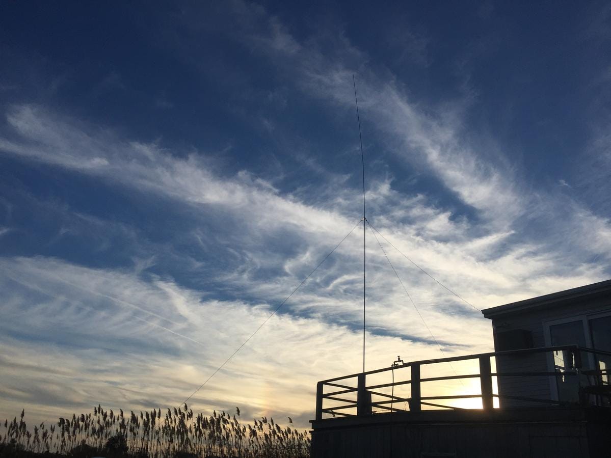
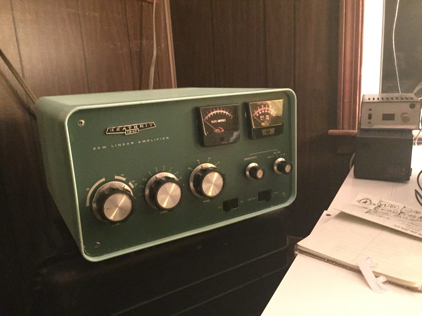
The resulting 50 Ohm feedpoint impedance enabled 100 Watt operation that first night, producing many contacts.4 The next day, a SB-221 linear amplifier was lugged up the stairs enabling 1 kilowatt to be pumped into the contraption. This established our initial presence on the 40 meter band from Succotash Salt Marsh.
A few days later, on December 23, 2018, a second vertical was installed at the edge of the salt marsh.
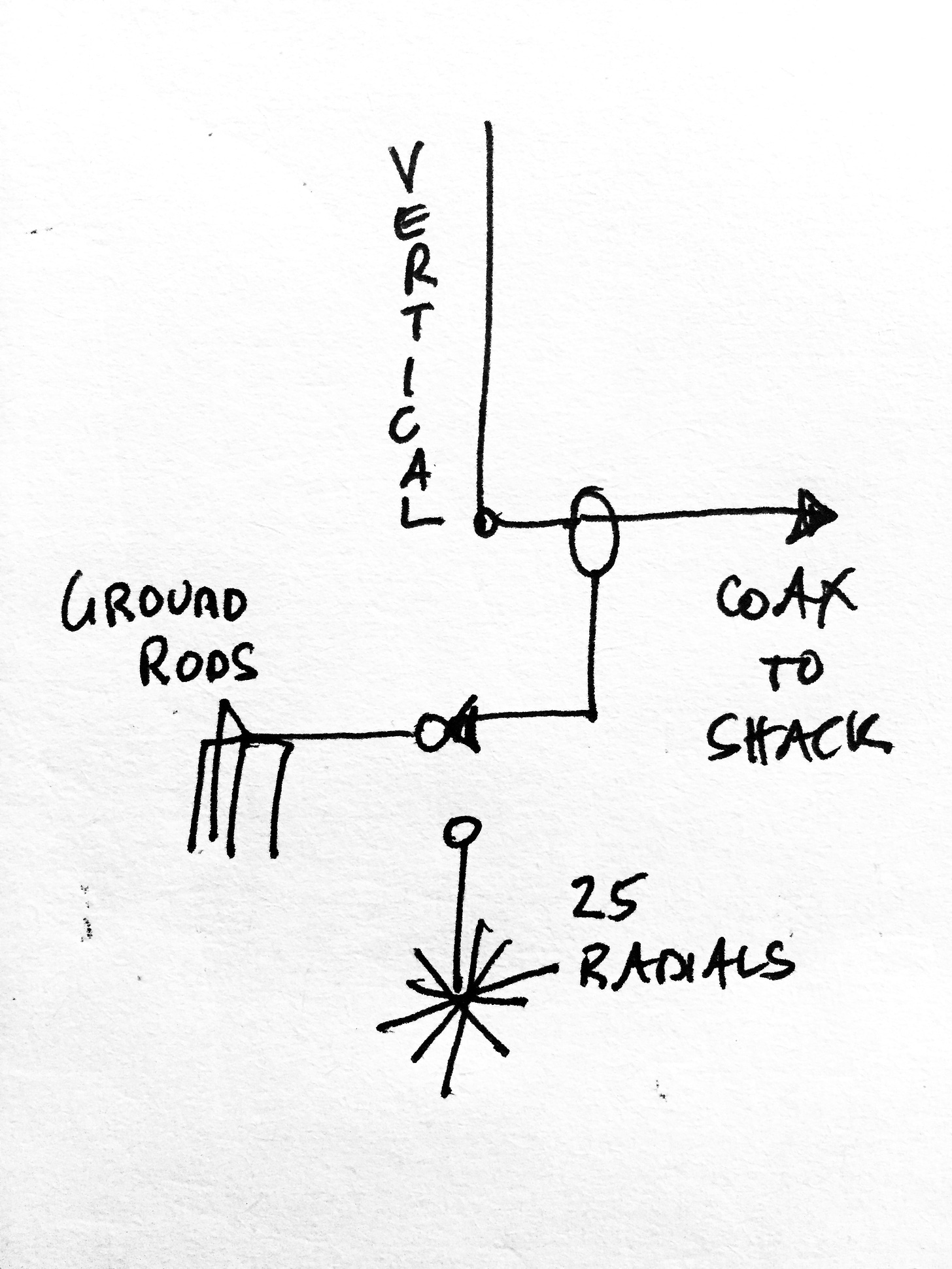
Its ground system was limited to four (4) 2.5’ copper pipes driven down into the marsh floor so its performance could be compared against the vertical on the deck, which now served as a reference antenna.
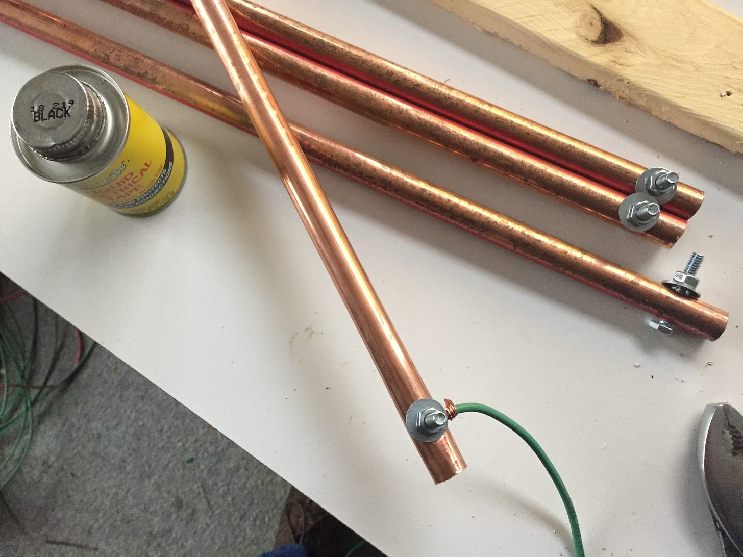
This was done in order to see what happens when the ground system under the “wet” vertical evolves from four (4) ground rods to 25 ground radials—as we shall shortly see.
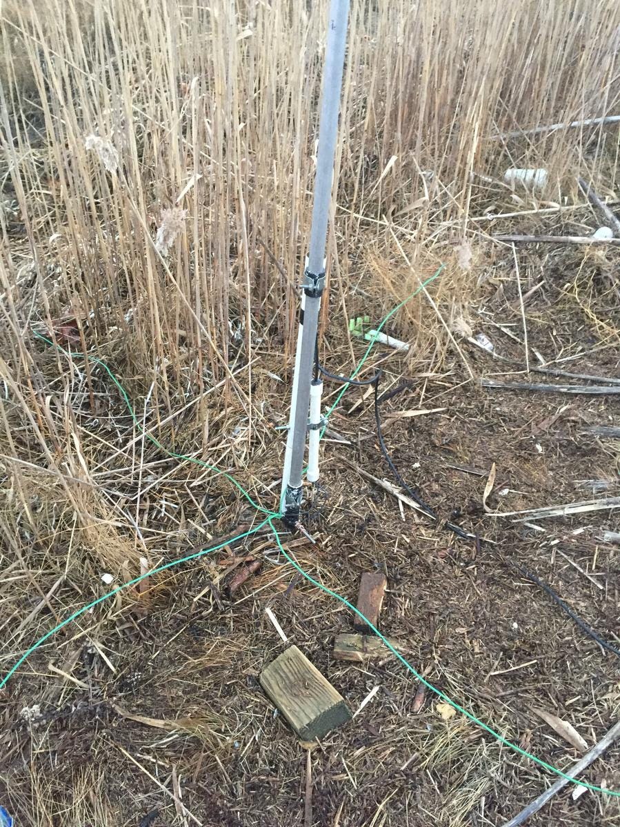
When swept with a MFJ 256B antenna analyzer, the four ground rods produce a 52 Ohm resonant feedpoint impedance at 7.155 MHz.

Calculating Radiation Efficiency
Since the resonant feedpoint impedance of a 1/4-wave vertical is around 36 Ohms, the 52 Ohms we get from the four ground rods is 16 Ohms more than the 36 Ohms we seek. This means that when we pump 1 KW into the vertical, we are pumping it through a 16 Ohm resistor in series with the 36 Ohm feedpoint load. This means only part of the 1 KW ends up getting radiated. The amount that gets radiated and the amount that gets wasted are equal to the values of the two resistances when expressed as percentages of the total 52 Ohm feedpoint resistance.
36 Ohms/52 Ohms = 36/52 = 0.69 => 69% radiated
16 Ohms/52 Ohms = 16/52 = 0.30 => 30% wasted
Thus a 1/4-wave vertical exhibiting a 52 Ohm input impedance results in a radiation efficiency of 69% with ground losses at 30%. If we pump 1 KW into it, 690 Watts gets radiated and 300 Watts gets wasted heating up the ground around the vertical.
Readers working with a 1/4-wave vertical should therefore not rejoice when it produces a 1:1 “perfect match”. If it does, more ground radials need to be added until the resonant feedpoint impedance drops to around 36 Ohms. The resulting SWR of 1.3 to 1 means the vertical is radiating at maximum efficiency.5
Adding Radials Lowers Take Off Angle?
Returning to our story, the first night of operating the two verticals produced interesting results. Whereas stateside stations reported no difference between the two aerials, DX stations reported the vertical on the deck being slightly louder than the “wet” vertical in the salt marsh. When we added radials to the “wet” vertical, things changed.
The experimental salt marsh vertical is beginning to pull away from the reference vertical. When we arrived at 15 radials, the two aerials were neck-to-neck. By 25 radials, South Africa, for example, is reporting 1 to 2 S-unit difference while stateside stations are reporting no significant difference. This suggests both verticals exhibit similar high-elevation envelopes.
— Field Notes, December 26, 2018
It also suggests that adding radials enhances the lower elevation envelope of a salt water vertical without attendant enhancement of its higher elevation envelope. This field observation appears to correlate the coupling of a vertical to salt water with the enhancement of its low elevation emissions. Thus the immersion of ground radials no deeper than 3” into the salt water might enhance a vertical’s emissions just above its pseudo-Brewster angle.
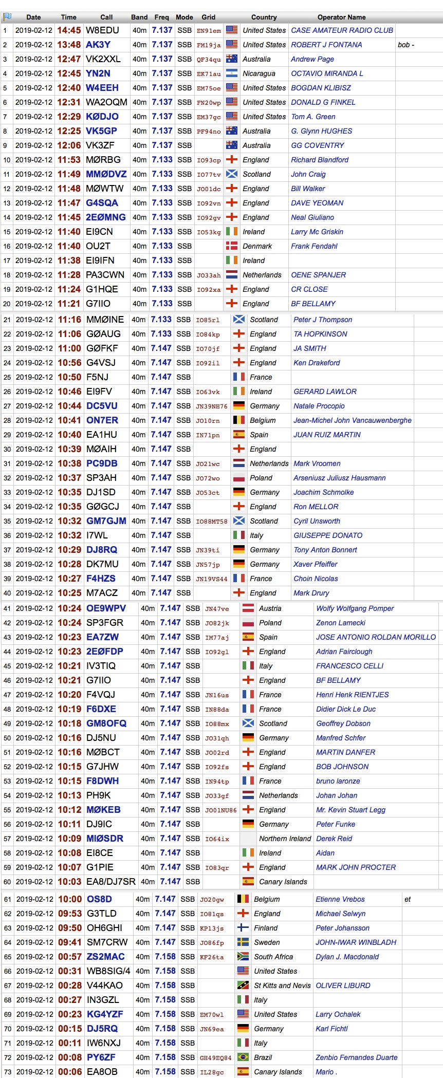
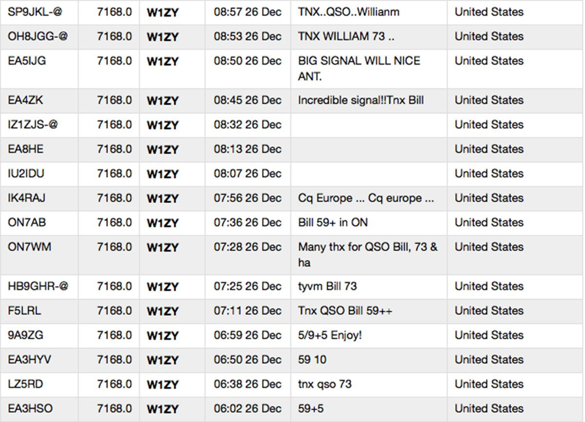
Readers may find interesting the DX Summit postings resulting from operation of the “wet” vertical with 25 ground radials, provided below.
Shootout: Radials vs Ground Rods
After comparing the two verticals as described, the reference vertical was dismantled so that it could be prepared for installation in the salt marsh.
While doing so, a second experiment was conducted wherein the “wet” vertical was toggled between its two ground systems by a relay at its base actuated in the shack.
Weird Results
Both DX and stateside stations reported seeing no difference in signal strength when the “wet” vertical was toggled between the two ground systems. This was odd because of the differences previously reported by DX and stateside stations when these ground systems were compared under separate verticals, as just described.
Whereas the differences in signal strength produced by the first test appear due to siting the ground systems (under separate verticals) at different locations, the second test suggests physically interlacing the ground systems under the same vertical electrically commingles them. This appears corroborated by sweeping the ground rods before and after deployment of the radials, as seen below.
The resonant feedpoint impedance of the four ground rods dropped from 52 Ohms to 37 Ohms after deploying 25 radials, reducing the ground loss from 16 Ohms to 1 Ohm. It also raised the resonant frequency of the vertical slightly.
(W)hen we laid-down the ground radials within the near field of the marsh vertical, we altered the ground rods' environment. We increased the density of return currents in the salty marsh mud around the base of the vertical in which the ground rods were sunk. Thus, the ground rods behaved differently; they were able to transfer more ground current to the vertical than when they were the only ground system installed underneath the vertical.
It is more likely that 25 ground radials altered the experience of the 4 ground rods than it is that the 4 ground rods affected the experience of the 25 ground radials. One system appeared to enhance the ability of the other system to pass ground current to the aerial.
Field Notes, January 2, 2019
The results suggest that the ground radials corralled near field return currents from a large area around the vertical which were then capacitively coupled to the ground rods due to the high permittivity of salt water.
INSERT DIAGRAM
Saltwater Permittivity as Dielectric
When engineers reference the high permittivity of salt water, they mean the extent to which it acts as a “dielectric” enhancing the flow of alternating currents between two conductors not touching each other. Conventionally, the vertical radiator is understood to be one of the conductors and its ground radial system is the other conductor. Our second experiment, however, established the ground rods and the ground radials as two conductors behaving as plates in a capacitor immersed in a dielectric of salt water. The permittivity of saltwater at 7 MHz was sufficient to cause the two ground systems to behave as if they were connected by a piece of wire.6
Thus when the relay connects to the ground rods, it might as well be connecting to the ground radials. And when connected to the ground radials, it might as well be connecting to the ground rods. The radials collected return currents so succinctly as to render inconsequential return currents collected by the ground rods.7 This explains why switching between the two made no difference to DX and stateside stations, and why sweeping the ground rods after installing radials produced the same results as sweeping the radials did.
Emerging from the Rabbit Hole
What this portends is that coupling a vertical to saltwater sculpts the shape of its radiation envelope—with tighter coupling elongating the lower elevation aspect of that envelope. It is likely this correlation is due to a monopole vertical’s emission of maximum energy at the horizon (0º). Thus horsing around with a vertical’s coupling to saltwater may be tantamount to horsing around with its emissions of energy at low elevation angles. And since the lower the elevation angle the more energy a vertical has to emit, coupling it to saltwater via “The Skin Effect” may constitute the practical limit of a vertical’s emission of (maximum) energy just above its pseudo-Brewster Angle.8
Final Analysis
After detailing the ELEA set up, we can now focus on reporting what happened when the verticals were operated within the earth’s terminator. As already indicated, on February 12, 2019, the initial ELEA transmission to Europe within the night/day terminator resulted in working DX stations we could not hear, requiring use of a remote receiver in the UK on which we could hear the ELEA signal coming through without any QSB or selective fading. This signal level was maintained on the remote UK receiver throughout the first test, which ended with contacts made in Northern Europe after local noon, CET.
The reports we received from DX stations we could not hear evidence great disparity, suggesting propagation from West to East through the night-day terminator was one-way. If the propagation was two-way, the discrepancy between signal reports might have been due to the inability of DX stations to transmit energy at elevation angles achieved by the phased verticals in the salt marsh, or that DX stations using horizontal antennas exhibited elevation nulls at those angles.
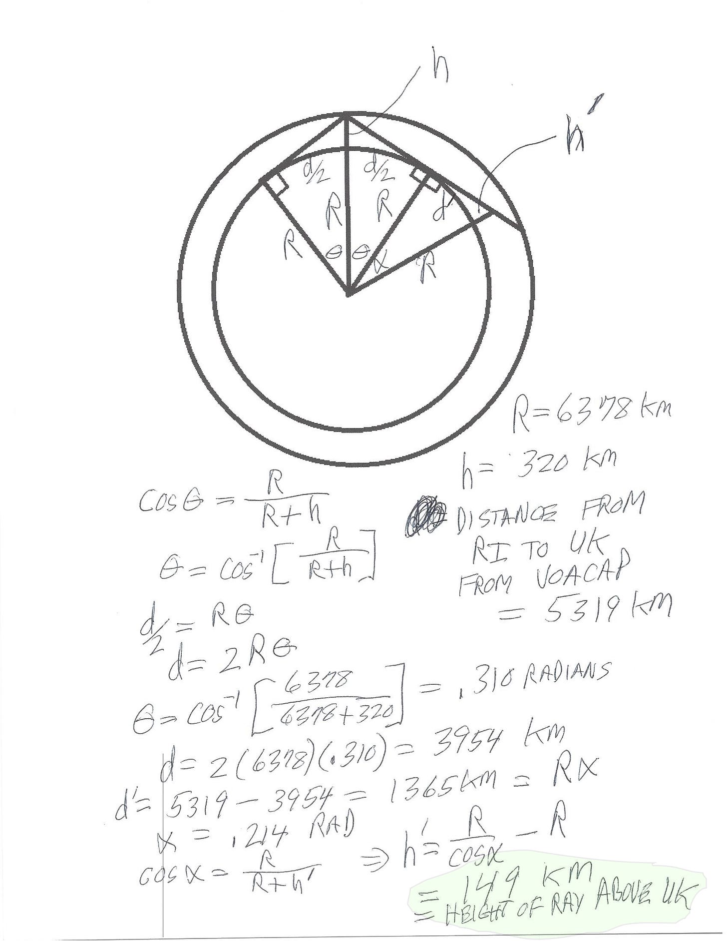
Jim Breakall, WA3FET, graciously calculated the elevation angles needed for a two-hop path to Europe from Rhode Island, assuming no ionospheric tilting. He first calculated how high a ray would be over London if emitted at the horizon (0˚) from Succotash Salt Marsh in Rhode Island.
WA3FET resolved that such a ray would end up being 149 km above the UK, or 93 miles. This rules out the possibility that energy emitted by the phased verticals just above its pseudo-Brewster angle made it to the remote receiver in the UK either via (i) line-of-sight or (ii) a single hop without ionospheric tilting. WA3FET then inspected VOCAP data and concluded that energy emitted at 8º would have made it to the remote receiver in two hops without any ionospheric tilting.
MORE TO FOLLOW →
Conclusion & Final Thoughts
Based on the documentation, our best guess is that the ELEA experiment transmitted a 7 MHz signal at an extremely low elevation angle encountering a region of the ionosphere exhibiting a protean index of refraction. And that this region is the same ionospheric region where chordal hop signals are refracted back down towards the earth. It is therefore posited that the ELEA signal was processed by this region as if it was a chordal hop signal on the last leg of its antipodal journey, and thus emerged from this region on the same earthbound trajectory as does a chordal hop signal after its last ionospheric bounce.
Do we know that this is true? No. It is merely a “guess” based on experimental data. Check out the video clip, below, in which Richard Feynman describes how experiments can sometimes produce unexpected results.
No field strength measurements were made at the transmit site to determine whether or not the salt marsh surface was energized as proposed. The only empirical data procured is the strength of Cap’n Jack’s signal on the UK receiver.
The “skin depth” of a conductor is how far below its surface you have to go before only 37% of its surface current remains flowing. On 7 MHz, this depth is about 3” below the surface of salt water.
The recording of South American contacts was made at local sunset on February 16, 2019, while the radials were still configured in an effort to enhance extremely low elevation emissions. This time, however, the verticals were oriented to the Southwest, which covers the Western half of South America. When listening carefully to the first contact with Southern Chile, readers may detect artifacts of QSB, such as selective fading and slight reduction of signal strength manifested by a rise in the noise floor behind the signal. It is hypothesized that such fading of the Chilean signal is due to the elevation nulls of the 2-element horizontal Yagi it used. In other words, as the wave angle of the propagation over this path changed, it is more likely that any attendant QSB artifacts originate from the horizontal transmitting antenna than it is the vertical receiving antennas.
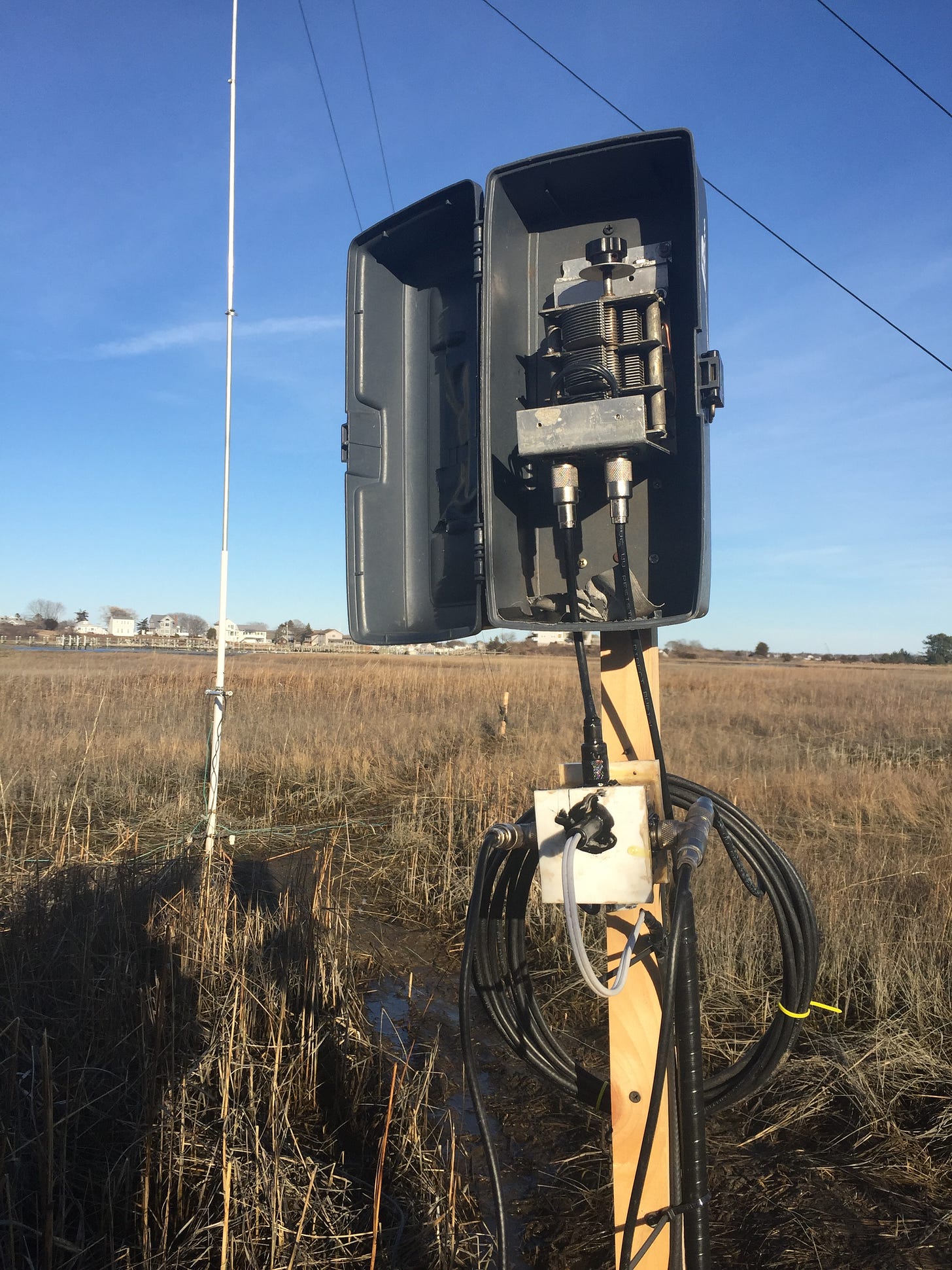
You can then add a matching network if your knickers are all bunched up over losses due to a 1.3:1 SWR along the coaxial feedline. This can be done at the feedpoint of a single vertical, but not for a pair of phased verticals without risking altering the phase relationship. In that case, you have to introduce the matching network where the feedline connects to the phasing system, as seen below. Click to enlarge.
In fact, the 1 Ohm of ground loss proffered by the ground rods after deployment of the radials might constitute the “dielectric loss” of this coupling. To find out, we would have to measure the ground loss offered by the radials after removal of the ground rods—which was never done.
A 16 Ohm resistor shunted by a 1 Ohm resistor.
Or 0.5º elevation on 7 MHz.


